~ My CCIE Wireless Journey & More…..


Configuring TPC
17 Sunday Mar 2013
Posted by nayarasi in RRM
≈ 4 Comments
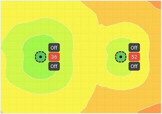
Controllers use the TPC (Tx Power Control) algorithm to determine whether the power of an AP needs to be adjusted down. Reducing the power of an AP helps mitigate co-channel interference with another AP on same channel in close proximity.
The TPC algorithm run in every 10 min (600s). Like DCA, the RF group leader runs TPC on per-radio, per AP basis. The more APs hear each other at -70dBm or greater, the better the TPC algorithm functions. Minimum requirement for TPC is that a single AP needs to be heard by at least 3 other APs at -70dBm or greater. Therefore you must have at least 4 APs total.
TPC use following criteria to determine if a power level change is necessary.
Step 1 . Are thre neighbors at -70 dBm or greater ? Step 2 . If step 1 satisfied, determine the transmit power using following equation.
Tx_Max for given AP + (Tx Power Control threshold – RSSI of third highest neighbor)
Step 3 . If the value from step 2 with current Tx power level ? Verify whether it exceeds the TPC hysteresis.
If the value is 6 dB or greater, the controller lower the power of the AP by one power level.
If the value is 3 dB , the AP increases its power. A power increase is almost always the result of not having 3rd neighbor.
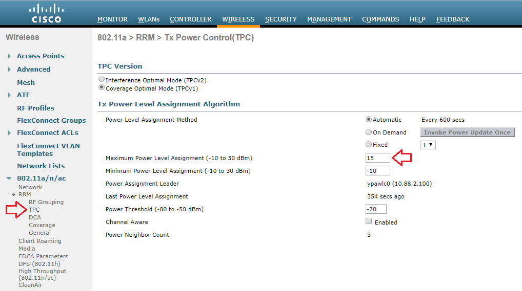
Here is the TPC configuration page (Wireless -> 802.11a/n or 802.11b/g/n -> RRM ->TPC).

Like DCA, we can select power assignment method for either TPC “Automatic”, “On Demand” or “Fixed” options. Default is “Automatic”.
Min & Max power level you can set. Value range is -10dBm to 30 dBm & default min is -10 & default max is 30.
Power Threshold is the cutoff signal level used by RRM to determine whether to reduce the power of an AP. Default threshold is -70dBm. Range is from -50 to -80. Increase this value (ie between -70 -50) causes the AP to operate at higher transmit power rates.Decreasing the value has opposite effect.
TPC page also shows few non-configurable parameter settings.
1 Power Neighbor Count : The minimum number of neighbors an AP must have for TPC algorithm to run. 2.Power Assignment Leader: The IP Address of RF group leader, who is responsible for power level assignment. 3.Last Power Level Assignmnet: The last time RRM evaluated current TPC assignment.
You can view the same information via CLI by “ show advanced {802.11a|802.11b} txpower ” command. Show below is for output of that command. Configurable settings are highlighted.
For example if you want to change TPC threshod to -75dBm via CLI you can use ” config advanced 802.11a tx-power-control-thresh -75 ”
In certain deployments where you have power-save clients you sometime needs to defer RRM’s normal off-channel scanning to avoid missing critical information from low volume clients ( eg medical devices that use power-save mode & send periodically telemetry info). You can configure off-channel scanning defer for a WLAN under advanced settings.

By default scan differ priority selected as “4,5,6” which means a AP has a packet UP value of 4 , 5 or 6 in its queue (to send to wireless client) it will defer the off-channel scanning by 100ms. You can change these setting via CLI as well.
When configuring this remember following UP values marking for downstream traffic
Bronze marks all downstream traffic to UP= 1 Silver marks all downstream traffic to UP= 0 Gold marks all downstream traffic to UP= 4 Platinum marks all downstream traffic to UP= 6
Related Posts
1. RRM Basics 2. Configuring RRM 3. Configuring DCA 4. Configuring CHD 5. Configuring ClientLink 6. Override RRM 7. 8. Rogue Access Point Detection
Share this:
4 thoughts on “configuring tpc”.
January 12, 2016 at 4:29 pm
Hi Tx_Max for given AP =Max Transmit Power ? How to get RSSI of third highest neighbor from wlc? Thanks
August 23, 2017 at 6:32 pm
what about warehouse deployments when antennas are LOS high in the ceiling but floor is full of racking.
August 29, 2017 at 2:44 pm
No experience in specific deployments in warehouse environment. I would check with someone who did such deployment
November 14, 2018 at 12:12 am
Hi Rasika! Thanks a lot for your blog!
I wonder, how does TPC handles disabled data rates in RF profile, when it works on Neighbor messages which are always on 1Mb/s and maximum power. It is denoted in RRM Whitepaper that:
“For 802.11b this means that the message is sent at power level 1 (always the highest power for a particular radio) at 1 Mbps, and for 5 GHz radio’s 6 Mbps. This function is hard coded into the radio firmware, there is no user control. NDP power and modulation is not changed by user configured data rates or power levels.”
If we disable some lowest data rates(e.g. 12Mb/s is first mandatory rate, lower DR’s disabled, all upper rates are supported), we significantly reduce AP’s cell boundary. Will TPC increase transmit power then, comparing to lowest data rates enabled? Shall we increase TPC thresholds manually this case?
Thanks! Artem
Leave a comment Cancel reply
My CCIE Wireless Journey & More.....
CCNP to CCIE level wireless tricks & training
Not Another Wireless Blog
Path to CCIE

- Already have a WordPress.com account? Log in now.
- Subscribe Subscribed
- Copy shortlink
- Report this content
- View post in Reader
- Manage subscriptions
- Collapse this bar
- Cisco ISE (Identity Services Engine)
- ENCOR (350-401)
- ENWLSD (300-425)
- Overview of Wireless Site Surveys
- Performing Walk-through Surveys
- Performing Layer 1 Site Surveys
- Overview of Predictive Site Surveys
- RRM Overview
- Transmit Power Control
- (RX-SOP) Receive Start of Packet
- Neighbour Discovery Protocol
- RF Profiles
- Out of Box RF Profile
- Powering APs
- Cisco Wireless Licensing
- Wireless Roaming Concepts
- Validate Mobility Messaging
- AP Redundancy
- Controller Failure Detection
- AP Fallback
- AP Prioritization
Transmit Power Control (TPC)
One of the functions that makes up the RRM operations is Transmit Power Control (TPC) . In this lesson, we’ll be taking a closer look at the TPC algorithm and how it works.
2.0 Wired and Wireless Infrastructure 2.3 Design radio management
APs can broadcast and operate using a number of different power levels. The higher the power is set on our APs, the bigger our coverage cell. Due to this, the transmit power configured on APs needs to be managed to reduce co-channel interference. Can you imagine having to manage the power on each AP manually? Even then, having to find the right transmit power for your environment? It would be a nightmare… Thankfully, TPC (Transmit Power Control) can manage this for us automatically.
TPC is an algorithm that runs on our wireless controller every 10 minutes by default. The main aim is to set an APs transmit power to its optimal value. This value will provide the best performance to clients whilst avoiding interference with other APs. As the AP will most likely have an antenna on the 2.4GHz and 5Ghz bands, TPC will run independently. There will be one transmit power set for the 2.4GHz radio and another for the 5GHz radio.
As the wireless controller has no idea how our wireless network is setup, NDP (Neighbour Discovery Protocol) is used to build the topology. Using the NDP frames, our WLC will The WLC looks for APs that can hear each other at -70dBm or greater . In addition for this, in order for the TPC algorithm to operate, the AP must be able to hear an additional 3 APs.
We might have scenarios where we have a number of wireless controllers within our deployment. If this is the case, the controller allocated as RF group leader will run the TPC algorithm.
Now that you understand how TPC operates, let’s take a look at how the algorithm works. Our wireless controller will use the following criteria to determine if a TPC change is required:
1. Can the AP detect three other APs at -70dBm? 2. Use the following formula to determine the transmit power: Tx_Max + (Tx Power Control threshold – RSSI of 3rd highest neighbour)
In order to minimise potential disruption, RRM will only make gradual changes to the transmit power. As such, RRM will only increase or decrease the power by 3dB (half or double the transmit power).
Configuration
In most cases, TPC doesn’t require any configuration to work. There might however be situations where the TPC algorithm needs to be tweaked.
TPC configuration can applied using either of the following options:
- RF Profiles.
It’s worth noting that some TPC parameters can only be configured globally. This includes;
- TPC Version.
- How TPC runs.
Global Configuration:
Remember that the TPC algorithm runs independently on each 802.11 band. As such, we have a global TPC configuration for the 2.4GHz band (802.11b/g/n/ax) and one for the 5GHz band (802.11a/n/ac/ax) . The 2.4GHz global configuration can be configured by navigating to: WIRELESS > 802.11b/g/n/ax > RRM > TPC The 5GHz global configuration on the other hand can be configured by navigating to: WIRELESS > 802.11a/n/ac/ax > RRM > TPC
There are a number of configurable options available to TPC global configuration. This includes:
- TPC run method.
- Maximum power level assignment.
- Minimum power level assignment.
- Power threshold.
TPC Version:
There are two methods of TPC available:
- TPCv1 (Coverage Optimal Mode).
- TPCv2 (Interference Optimal Mode).
Unless you have a specific reason otherwise, it’s recommended to use the default TPCv1 – Coverage Optimal Mode .
TPC Run Method:
TPC can run using one of the following methods:
Minimum / Maximum Power Level Assignment:
These thresholds can be used to set the minimum or maximum amount of power that APs can use within the environment.
Power Threshold:
Finally, this is the cutoff used by RRM to determine whether it should reduce an APs power. An increase of the power threshold will cause the AP to operate at higher transmit power rates. A decrease of the threshold on the other hand will cause the AP to operate at lower transmit power rates.
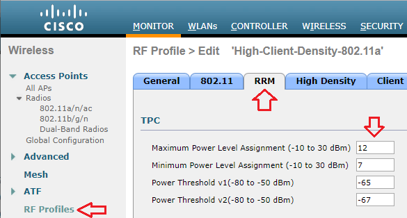
RF Profile:
Alternately, we can control TPC parameters using RF profiles. Our RF profile can then be applied to AP groups to control TPC on specific APs. In our example, I’ve created an RF profile called MN_RF-Profile-2.4GHz .
The TPC parameters can be configured under the RRM tab of our RF profile. We can then amend the following configuration parameters:
- Maximum Power Level Assignment.
- Minimum Power Level Assignment.
- Power Threshold v1.
- Power Threshold v2.
| / | : Vendor Configurations Overview |
Enabling 802.11 a/n/ac and 802.11 b/g/n
802.11 a/n/ac and 802.11 b/g/n helps reduce the power of a radio transmitter to the minimum necessary to maintain the link with a certain quality.
Global Parameters Settings
- Click Wireless to access the All APs page.
802.11a Global Parameters or 802.11b Global Parameters page appears.

- Disable lower data rates for maximum reliability. You must enable one Mandatory higher data rate. Data rates are selected based on sites.
- Perform a voice quality site survey to ensure proper network coverage before installing Vocera.
- Click Apply . Your changes are committed.
Tx Power Control Settings
- Navigate to 802.11 a/n/ac or 802.11 b/g/n > RRM > TPC .

Power Level Assignment —Automatic.
Power Threshold (-80 to -50 dBm) — -70dB.
Power changes are only made when an AP's third loudest neighbor is heard at a signal level higher than the default value of -70 dBm.
- Click Save Configuration . Your changes are saved.
Configuring Coverage
To configure coverage using 802.11 a/n/ac or 802.11 b/g/n, perform the following task:

Voice RSSI (-60 to -90 dBm) — -70 .
Min Failed Client Count per AP — 12 .
- Click Apply Commits your changes.
- Click Save Configuration Saves your changes. Note: Wait for at least 60 minutes after enabling dynamic power level assignment to allow the WLAN to stabilize. Each WLAN has its unique characteristics, based on the structural features of the facility, density of APs, activity levels, and many other factors. Therefore, achieving optimal coverage is an iterative process. The goal of this iterative configuration process is to have the APs transmit power set to level 3 under normal conditions.
- Verify AP transmit power levels and coverage.
Power Assignment in Radio Networks with Two Power Levels
- Published: 24 January 2007
- Volume 47 , pages 183–201, ( 2007 )
Cite this article

- Paz Carmi 1 &
- Matthew J. Katz 1
161 Accesses
25 Citations
Explore all metrics
We study the power-assignment problem in radio networks, where each radio station can transmit in one of two possible power levels, corresponding to two ranges—short and long. We show that this problem is NP-hard, and we present an O(n 2 )-time assignment algorithm such that the number of transmitters that are assigned long range by the algorithm is at most (11/6) times the number of transmitters that are assigned long range by an optimal algorithm. We also present a (9/5)-approximation algorithm for this problem whose running time is considerably higher.
This is a preview of subscription content, log in via an institution to check access.
Access this article
Subscribe and save.
- Get 10 units per month
- Download Article/Chapter or Ebook
- 1 Unit = 1 Article or 1 Chapter
- Cancel anytime
Price includes VAT (Russian Federation)
Instant access to the full article PDF.
Rent this article via DeepDyve
Institutional subscriptions
Large Neighborhood Search

Expected utility theory with probability grids and preference formation

The p-Median Problem
Author information, authors and affiliations.
Department of Computer Science, Ben-Gurion University of the Negev, Beer-Sheva 84105, Israel
Paz Carmi & Matthew J. Katz
You can also search for this author in PubMed Google Scholar
Corresponding authors
Correspondence to Paz Carmi or Matthew J. Katz .
Rights and permissions
Reprints and permissions
About this article
Carmi, P., Katz, M. Power Assignment in Radio Networks with Two Power Levels. Algorithmica 47 , 183–201 (2007). https://doi.org/10.1007/s00453-006-1230-1
Download citation
Received : 22 December 2004
Published : 24 January 2007
Issue Date : February 2007
DOI : https://doi.org/10.1007/s00453-006-1230-1
Share this article
Anyone you share the following link with will be able to read this content:
Sorry, a shareable link is not currently available for this article.
Provided by the Springer Nature SharedIt content-sharing initiative
- Power Level
- Vertex Cover
- Optimal Assignment
- Communication Graph
- Find a journal
- Publish with us
- Track your research
Wait, but Wi-Fi?
Transmit Power Control Considerations
Proper configuration of Transmit Power Control (TPC) settings can help to ensure that your Access Point (AP) does not speak too loudly. If your AP is transmitting at 18dBm and an associated client station (STA) is at the cell edge and only capable of transmitting at 15dBm, your client will be able to hear the AP transmission, but the AP won’t be able to hear the client which leads to retransmissions and thus reduced performance.
Wireless network design is ultimately dependent upon the clients it is to support, so we will want to have an idea of what our intended clients are capable of. As an example, one of my customer’s clients is an HP EliteBook 8470p laptop workstation which has a Broadcom BCM943228HM4L Wi-Fi adapter. According to the product specification web page for this particular model, I was able to find that it is capable of transmitting at around 15dBm. If this is my customer’s least capable device, I would not want my AP to transmit louder than 15dBm either.
My customer is using a Cisco 3504 Wireless Controller running AireOS version 8.8. I am able to globally configure the Maximum Power Level Assignment to 15dBm.
If the same controller were managing multiple locations with different requirements, I can also set a Maximum Power Level Assignment for different RF Profiles.
Though the maximum power level is configured in dBm, Cisco uses a series of numbers to represent levels of power. Phil Morgan of NC-Expert wrote an article titled WLC and AP Power settings in which he discusses Cisco power levels in further detail. In his article, he discusses how we can determine what the power levels represent as they vary by AP model, band (2.4 vs 5GHz), and even channel groupings (i.e. U-NII 1, 2, 2e, 3).
I also stumbled upon an excellent post by Maxim Risman in the Cisco Community titled Cisco Access point 2802i Tx Power Chart where he demonstrates the use of another very helpful command which summarizes the power levels of all APs: show advanced 802.11a txpower
Note that the range for the power levels actually does not change, but rather TPC is limiting the highest level that can be used.
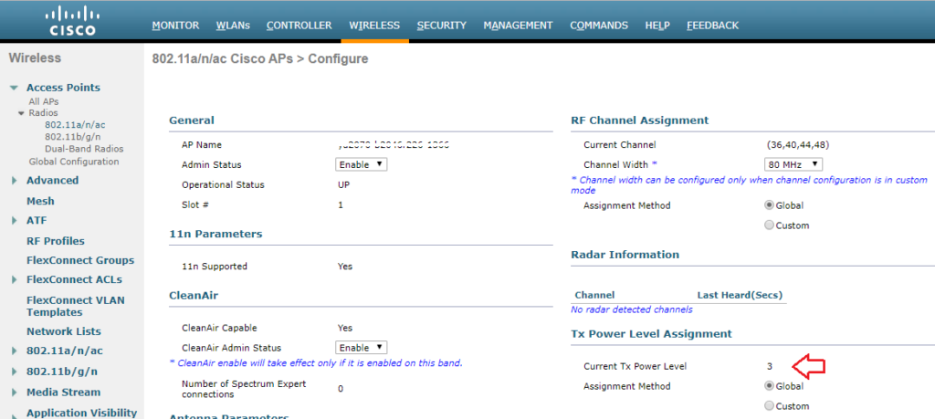
The current power level setting can also be found in the web GUI by navigating to Wireless > Access Points > Radios. There, you can see the power level for all of your APs in a column, or you can dive in to the configuration of a radio.
When performing predictive site surveys with Ekahau Pro site survey software, we have the ability to adjust the transmit power with which to generate our expected heat maps.
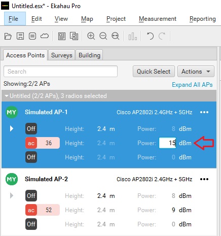
We can get an idea of how this difference may affect our design in the real world.
If you are interested in getting deeper into Cisco’s TPC implementation, you may want to check out a whitepaper they have published titled Transmit Power Control (TPC) Algorithm .

Published by Stephen
View all posts by Stephen
- Skip to content
- Skip to search
- Skip to footer
Cisco Catalyst 9800 Series Wireless Controller Software Configuration Guide, Cisco IOS XE Cupertino 17.7.x
Bias-free language.
The documentation set for this product strives to use bias-free language. For the purposes of this documentation set, bias-free is defined as language that does not imply discrimination based on age, disability, gender, racial identity, ethnic identity, sexual orientation, socioeconomic status, and intersectionality. Exceptions may be present in the documentation due to language that is hardcoded in the user interfaces of the product software, language used based on RFP documentation, or language that is used by a referenced third-party product. Learn more about how Cisco is using Inclusive Language.
- Overview of the Controller
- New Configuration Model
- Wireless Management Interface
- BIOS Protection
- Smart Licensing Using Policy
- Boot Integrity Visibility
- Management over Wireless
- SUDI99 Certificate Support
- Link Aggregation Group
- Best Practices
- Upgrading the Cisco Catalyst 9800 Wireless Controller Software
- In-Service Software Upgrade
- Software Maintenance Upgrade
- Efficient Image Upgrade
- Predownloading an Image to an Access Point
- N+1 Hitless Rolling AP Upgrade
- NBAR Dynamic Protocol Pack Upgrade
- Wireless Sub-Package for Switch
- Country Codes
- Regulatory Compliance (Rest of the World) for Domain Reduction
- Sniffer Mode
- Monitor Mode
- AP Priority
- FlexConnect
- OEAP Link Test
- Cisco OEAP Split Tunneling
- AP Crash File Upload
- Access Point Plug-n-Play
- 802.11 Parameters for Cisco Access Points
- 802.1x Support
- CAPWAP Link Aggregation Support
- DHCP and NAT Functionality on Root Access Point
- OFDMA Support for 11ax Access Points
- AP Audit Configuration
- AP Support Bundle
- Cisco Flexible Antenna Port
- LED States for Access Points
- Access Points Memory Information
- Real-Time Access Points Statistics
- Access Point Tag Persistency
Radio Resource Management
- Coverage Hole Detection
- Optimized Roaming
- Cisco Flexible Radio Assignment
- XOR Radio Support
- Cisco Receiver Start of Packet
- Client Limit
- Unscheduled Automatic Power Save Delivery
- Target Wake Time
- Enabling USB Port on Access Points
- Dynamic Frequency Selection
- Cisco Access Points with Tri-Radio
- Cisco Catalyst Center Assurance Wi-Fi 6 Dashboard
- Antenna Disconnection Detection
- Neighbor Discovery Protocol Mode on Access Points
- 6-GHz Band Operations
- AP Packet Capture
- DHCP Option82
- RADIUS Realm
- RADIUS Accounting
- RADIUS Call Station Identifier
- Cisco StadiumVision
- Persistent SSID Broadcast
- Network Monitoring
- Creating a Lobby Ambassador Account
- Lobby Ambassador Account
- Guest User Accounts
- Link Local Bridging
- Web Admin Settings
- Network Mobility Services Protocol
- Application Visibility and Control
- Software-Defined Application Visibility and Control
- Cisco Hyperlocation
- FastLocate for Cisco Catalyst Series Access Points
- IoT Services Management
- IoT Module Management in the Controller
- Cisco Spaces
- EDCA Parameters
- Adaptive Client Load-Based EDCA
- 802.11 parameters and Band Selection
- NBAR Protocol Discovery
- Conditional Debug, Radioactive Tracing, and Packet Tracing
- Aggressive Client Load Balancing
- Accounting Identity List
- Support for Accounting Session ID
- Wireless Multicast
- Map-Server Per-Site Support
- Volume Metering
- Enabling Syslog Messages in Access Points and Controller for Syslog Server
- Login Banner
- Wi-Fi Alliance Agile Multiband
- Disabling Clients with Random MAC Address
- Dataplane Packet Logging
- Streaming Telemetry
- Wireless Clients Threshold Warning
- MAC Filtering
- Web-Based Authentication
- Central Web Authentication
- Private Shared Key
- Multi-Preshared Key
- Multiple Authentications for a Client
- Wi-Fi Protected Access 3
- IP Source Guard
- Management Frame Protection
- DNS-Based Access Control Lists
- Allowed List of Specific URLs
- Cisco Umbrella WLAN
- RADIUS Server Load Balancing
- AAA Dead-Server Detection
- ISE Simplification and Enhancements
- RADIUS DTLS
- Policy Enforcement and Usage Monitoring
- Local Extensible Authentication Protocol
- Local EAP Ciphersuite
- Authentication and Authorization Between Multiple RADIUS Servers
- Secure LDAP
- Network Access Server Identifier
- Locally Significant Certificates
- Certificate Management
- Controller Self-Signed Certificate for Wireless AP Join
- Managing Rogue Devices
- Classifying Rogue Access Points
- Advanced WIPS
- Cisco TrustSec
- SGT Inline Tagging and SXPv4
- Multiple Cipher Support
- Configuring Secure Shell
- Encrypted Traffic Analytics
- Internet Protocol Security
- Transport Layer Security Tunnel Support
- IP MAC Binding
- Disabling IP Learning in FlexConnect Mode
- NAT Support on Mobility Groups
- Static IP Client Mobility
- Mobility Domain ID - Dot11i Roaming
- 802.11r Support for Flex Local Authentication
- Opportunistic Key Caching
- High Availability
- Quality of Service
- Wireless Auto-QoS
- Native Profiling
- Air Time Fairness
- IPv6 Non-AVC QoS Support
- QoS Basic Service Set Load
- IPv6 Client IP Address Learning
- IPv6 Client Mobility
- IPv6 Support on Flex and Mesh
- IPv6 CAPWAP UDP Lite Support
- Neighbor Discovery Proxy
- Address Resolution Protocol Proxy
- IPv6 Ready Certification
- Cisco CleanAir
- Bluetooth Low Energy
- Persistent Device Avoidance
- Spectrum Intelligence
- Spectrum Analysis
- Mesh Access Points
- Redundant Root Access Point (RAP) Ethernet Daisy Chaining
- VideoStream
- Software-Defined Access Wireless
- Passive Client
- Fabric in a Box with External Fabric Edge
- VLAN Groups
- WLAN Security
- Remote LANs
- RLAN External Module
- 802.11ax Per WLAN
- BSS Coloring
- DHCP for WLANs
- Aironet Extensions IE (CCX IE)
- Device Analytics
- BSSID Counters
- Workgroup Bridges
- Peer-to-Peer Client Support
- Deny Wireless Client Session Establishment Using Calendar Profiles
- Ethernet over GRE
- Wireless Guest Access
- Wired Guest Access
- Express Wi-Fi by Facebook
- User Defined Network
- Hotspot 2.0
- Client Roaming Across Policy Profile
- Assisted Roaming
- 802.11r BSS Fast Transition
- Cisco DNA Service for Bonjour Solution Overview
- Configuring Local and Wide Area Bonjour Domains
- Configuring Local Area Bonjour for Wireless Local Mode
- Configuring Local Area Bonjour for Wireless FlexConnect Mode
- Configuration Example for Local Mode - Wireless and Wired
- Configuration Example for FlexConnect Mode - Wireless and Wired
- Multicast Domain Name System

Chapter: Radio Resource Management
Radio resource monitoring, rf group leader, rf group name, rogue access point detection in rf groups, secure rf groups, transmit power control, overriding the tpc algorithm with minimum and maximum transmit power settings, dynamic bandwidth selection, coverage hole detection and correction, cisco ai enhanced rrm, restrictions for radio resource management, configuring neighbor discovery type (gui), configuring neighbor discovery type (cli), configuring rf group selection mode (gui), configuring rf group selection mode (cli), configuring an rf group name (cli), configuring a secure rf group (cli), configuring members in an 802.11 static rf group (gui), configuring members in an 802.11 static rf group (cli), configuring transmit power (gui), configuring the tx-power control threshold (cli), configuring the tx-power level (cli), configuring advanced 802.11 channel assignment parameters (gui), configuring advanced 802.11 channel assignment parameters (cli), configuring 802.11 coverage hole detection (gui), configuring 802.11 coverage hole detection (cli), configuring 802.11 event logging (cli), configuring 802.11 statistics monitoring (gui), configuring 802.11 statistics monitoring (cli), configuring the 802.11 performance profile (gui), configuring the 802.11 performance profile (cli), enabling channel assignment (gui), enabling channel assignment (cli), restarting dca operation, updating power assignment parameters (gui), updating power assignment parameters (cli), configuring rogue access point detection in rf groups (cli), monitoring rrm parameters, verifying rf group status (cli), examples: rf group configuration, configuring ed-rrm on the cisco wireless controller (cli), information about radio resource management.
The Radio Resource Management (RRM) software that is embedded in the device acts as a built-in Radio Frequency (RF) engineer to consistently provide real-time RF management of your wireless network. RRM enables devices to continually monitor their associated lightweight access points for the following information:
Traffic load—The total bandwidth used for transmitting and receiving traffic. It enables wireless LAN managers to track and plan network growth ahead of client demand.
Interference—The amount of traffic coming from other 802.11 sources.
Noise—The amount of non-802.11 traffic that is interfering with the currently assigned channel.
Coverage—The Received Signal Strength (RSSI) and signal-to-noise ratio (SNR) for all connected clients.
Other —The number of nearby access points.
RRM performs these functions:
Radio resource monitoring
Power control transmission
Dynamic channel assignment
Coverage hole detection and correction
RF grouping
RRM automatically detects and configures new devices and lightweight access points as they are added to the network. It then automatically adjusts the associated and nearby lightweight access points to optimize coverage and capacity.
Lightweight access points can scan all the valid channels for the country of operation as well as for channels available in other locations. The access points in local mode go offchannel for a period not greater than 70 ms to monitor these channels for noise and interference. Packets collected during this time are analyzed to detect rogue access points, rogue clients, ad-hoc clients, and interfering access points.
Each access point spends only 0.2 percent of its time off channel. This activity is distributed across all the access points so that adjacent access points are not scanning at the same time, which could adversely affect wireless LAN performance.
Information About RF Groups
An RF group is a logical collection of controllers that coordinate to perform RRM in a globally optimized manner to perform network calculations on a per-radio basis. Separate RF groups exist for 2.4-GHz and 5-GHz networks. Clustering Cisco Catalyst 9800 Series Wireless Controller into a single RF group enables the RRM algorithms to scale beyond the capabilities of a single Cisco Catalyst 9800 Series Wireless Controller .
An RF group is created based on the following parameters:
User-configured RF network name.
Neighbor discovery performed at the radio level.
Country list configured on the controller.
RF grouping runs between controllers .
Lightweight access points periodically send out neighbor messages over the air. Access points using the same RF group name validate messages from each other.
When access points on different controllers hear validated neighbor messages at a signal strength of –80 dBm or stronger, the controllers dynamically form an RF neighborhood in auto mode. In static mode, the leader is manually selected and the members are added to the RF Group.
| , but they are different in terms of their use. An RF group facilitates scalable, system-wide dynamic RF management, while a mobility group facilitates scalable, system-wide mobility and controller redundancy. |
RF Group Leader can be configured in two ways as follows:
Auto Mode: In this mode, the members of an RF group elect an RF group leader to maintain a primary power and channel scheme for the group. The RF grouping algorithm dynamically chooses the RF group leader and ensures that an RF group leader is always present. Group leader assignments can and do change (for instance, if the current RF group leader becomes inoperable or RF group members experience major changes).
Static Mode: In this mode, a user selects a controller as an RF group leader manually. In this mode, the leader and the members are manually configured and fixed. If the members are unable to join the RF group, the reason is indicated. The leader tries to establish a connection with a member every minute if the member has not joined in the previous attempt.
The RF group leader analyzes real-time radio data collected by the system, calculates the power and channel assignments, and sends them to each of the controllers in the RF group. The RRM algorithms ensure system-wide stability, and restrain channel and power scheme changes to the appropriate local RF neighborhoods.
| becomes both leader and member for a specific radio, you get to view the IPv4 and IPv6 address as part of the group leader. When a Controller A becomes a member and Controller B becomes a leader, the Controller A displays either IPv4 or IPv6 address of Controller B using the address it is connected. So, if both leader and member are not the same, you get to view only one IPv4 or IPv6 address as a group leader in the member. |
If Dynamic Channel Assignment (DCA) needs to use the worst-performing radio as the single criterion for adopting a new channel plan, it can result in pinning or cascading problems.
The main cause of both pinning and cascading is that any potential channel plan changes are controlled by the RF circumstances of the worst-performing radio. The DCA algorithm does not do this; instead, it does the following:
Multiple local searches: The DCA search algorithm performs multiple local searches initiated by different radios in the same DCA run rather than performing a single global search that is driven by a single radio. This change addresses both pinning and cascading, while maintaining the desired flexibility and adaptability of DCA and without jeopardizing stability.
Multiple Channel Plan Change Initiators (CPCIs): Previously, the single worst radio was the sole initiator of a channel plan change. Now each radio in an RF group is evaluated and prioritized as a potential initiator. Intelligent randomization of the resulting list ensures that every radio is eventually evaluated, which eliminates the potential for pinning.
Limiting the propagation of channel plan changes (Localization): For each CPCI radio, the DCA algorithm performs a local search for a better channel plan, but only the CPCI radio itself and its one-hop neighboring access points are actually allowed to change their current transmit channels. The impact of an access point triggering a channel plan change is felt only to within two RF hops from that access point, and the actual channel plan changes are confined to within a one-hop RF neighborhood. Because this limitation applies across all CPCI radios, cascading cannot occur.
Non-RSSI-based cumulative cost metric: A cumulative cost metric measures how well an entire region, neighborhood, or network performs with respect to a given channel plan. The individual cost metrics of all the access points in that area are considered in order to provide an overall understanding of the channel plan’s quality. These metrics ensure that the improvement or deterioration of each single radio is factored into any channel plan change. The objective is to prevent channel plan changes in which a single radio improves, but at the expense of multiple other radios experiencing a considerable performance decline.
The RRM algorithms run at a specified updated interval, which is 600 seconds by default. Between update intervals, the RF group leader sends keepalive messages to each of the RF group members and collects real-time RF data.
RF Grouping Failure Reason Codes
RF Grouping failure reason codes and their explanations are listed below:
| Reason Code | Description |
|---|---|
| 1 | Maximum number (20) of controllers are already present in the group. |
| 2 | If the following conditions are met: OR |
| 3 | Group ID do not match. |
| 4 | Request does not include source type. |
| 5 | Group spilt message to all member while group is being reformed. |
| 6 | Auto leader is joining a static leader, during the process deletes all the members. |
| 9 | Grouping mode is turned off. |
| 11 | Country code does not match. |
| 12 | Controller is up in hierarchy compared to sender of join command (static mode). Requestor is up in hierarchy (auto mode). |
| 13 | Controller is configured as static leader and receives join request from another static leader. |
| 14 | Controller is already a member of static group and receives a join request from another static leader. |
| 15 | Controller is a static leader and receives join request from non-static member. |
| 16 | Join request is not intended to the controller. Controller name and IP do not match. |
| 18 | RF domain do not match. |
| 19 | Controller received a Hello packet at incorrect state. |
| 20 | Controller has already joined Auto leader, now gets a join request from static leader. |
| 21 | Group mode change. Domain name change from CLI. Static member is removed from CLI. |
| 22 | Max switch size (350) is reached |
Additional Reference
Radio Resource Management White Paper : https://www.cisco.com/c/en/us/td/docs/wireless/controller/technotes/8-3/b_RRM_White_Paper/b_RRM_White_Paper_chapter_011.html
A controller is configured in an RF group name, which is sent to all the access points joined to the controller and used by the access points as the shared secret for generating the hashed MIC in the neighbor messages. To create an RF group, you configure all of the controllers to be included in the group with the same RF group name.
If there is any possibility that an access point joined to a controller might hear RF transmissions from an access point on a different controller , you should configure the controller with the same RF group name. If RF transmissions between access points can be heard, then system-wide RRM is recommended to avoid 802.11 interference and contention as much as possible.
After you have created an RF group of controller , you need to configure the access points connected to the controller to detect rogue access points. The access points will then select the beacon or probe-response frames in neighboring access point messages to see if they contain an authentication information element (IE) that matches that of the RF group. If the selection is successful, the frames are authenticated. Otherwise, the authorized access point reports the neighboring access point as a rogue, records its BSSID in a rogue table, and sends the table to the controller .
Secure RF groups enable to encrypt and secure RF grouping and RRM message exchanges over DTLS tunnel. During the DTLS handshake controllers authenticate each other with wireless management trust-point certificate.
The device dynamically controls access point transmit power based on the real-time wireless LAN conditions.
The Transmit Power Control (TPC) algorithm increases and decreases an access point’s power in response to changes in the RF environment. In most instances, TPC seeks to lower an access point's power to reduce interference, but in the case of a sudden change in the RF coverage, for example, if an access point fails or becomes disabled, TPC can also increase power on the surrounding access points. This feature is different from coverage hole detection, which is primarily concerned with clients. TPC provides enough RF power to achieve the required coverage levels while avoiding channel interference between access points. We recommend that you select TPCv1; TPCv2 option is deprecated. With TPCv1, you can select the channel aware mode; we recommend that you select this option for 5 GHz, and leave it unchecked for 2.4 GHz.
The TPC algorithm balances RF power in many diverse RF environments. However, it is possible that automatic power control will not be able to resolve some scenarios in which an adequate RF design was not possible to implement due to architectural restrictions or site restrictions, for example, when all the access points must be mounted in a central hallway, placing the access points close together, but requiring coverage to the edge of the building.
In these scenarios, you can configure maximum and minimum transmit power limits to override TPC recommendations. The maximum and minimum TPC power settings apply to all the access points through RF profiles in a RF network.
To set the Maximum Power Level Assignment and Minimum Power Level Assignment, enter the maximum and minimum transmit power used by RRM in the fields in the Tx Power Control window. The range for these parameters is -10 to 30 dBm. The minimum value cannot be greater than the maximum value; the maximum value cannot be less than the minimum value.
If you configure a maximum transmit power, RRM does not allow any access point attached to the controller, to exceed this transmit power level (whether the power is set by RRM TPC or by coverage hole detection). For example, if you configure a maximum transmit power of 11 dBm, no access point will transmit above 11 dBm, unless the access point is configured manually.
Cisco APs support power level changes in 3 dB granularity. TPC Min and Max power settings allow for values in 1 dB increments. The resulting power level will be rounded to the nearest value supported in the allowed powers entry for the AP model and the current serving channel.
Each AP model has its own set of power levels localized for its regulatory country and region. Moreover, the power levels for the same AP model will vary based on the band and channel it is set to. For more information on Allowed Power Level vs. Actual power(in dBm), use the show ap name <name> config slot <0|1|2|3> command to view the specific number of power levels, the range of power levels allowed, and the current power level setting on the AP.
Dynamic Channel Assignment
Two adjacent access points on the same channel can cause either signal contention or signal collision. In a collision, data is not received by the access point. This functionality can become a problem, for example, when someone reading an e-mail in a café affects the performance of the access point in a neighboring business. Even though these are separate networks, someone sending traffic to the café on channel 1 can disrupt communication in an enterprise using the same channel. Devices can dynamically allocate access point channel assignments to avoid conflict and increase capacity and performance. Channels are reused to avoid wasting scarce RF resources. In other words, channel 1 is allocated to a different access point far from the café, which is more effective than not using channel 1 altogether.
The device ’s Dynamic Channel Assignment (DCA) capabilities are also useful in minimizing adjacent channel interference between access points. For example, two overlapping channels in the 802.11b/g band, such as 1 and 2, cannot simultaneously use 11 or 54 Mbps. By effectively reassigning channels, the device keeps adjacent channels that are separated.
The device examines a variety of real-time RF characteristics to efficiently handle channel assignments as follows:
Access point received energy: The received signal strength measured between each access point and its nearby neighboring access points. Channels are optimized for the highest network capacity.
Noise: Noise can limit signal quality at the client and access point. An increase in noise reduces the effective cell size and degrades user experience. By optimizing channels to avoid noise sources, the device can optimize coverage while maintaining system capacity. If a channel is unusable due to excessive noise, that channel can be avoided.
802.11 interference: Interference is any 802.11 traffic that is not a part of your wireless LAN, including rogue access points and neighboring wireless networks. Lightweight access points constantly scan all the channels looking for sources of interference. If the amount of 802.11 interference exceeds a predefined configurable threshold (the default is 10 percent), the access point sends an alert to the device . Using the RRM algorithms, the device may then dynamically rearrange channel assignments to increase system performance in the presence of the interference. Such an adjustment could result in adjacent lightweight access points being on the same channel, but this setup is preferable to having the access points remain on a channel that is unusable due to an interfering foreign access point.
In addition, if other wireless networks are present, the device shifts the usage of channels to complement the other networks. For example, if one network is on channel 6, an adjacent wireless LAN is assigned to channel 1 or 11. This arrangement increases the capacity of the network by limiting the sharing of frequencies. If a channel has virtually no capacity remaining, the device may choose to avoid this channel. In huge deployments in which all nonoverlapping channels are occupied, the device does its best, but you must consider RF density when setting expectations.
Load and utilization: When utilization monitoring is enabled, capacity calculations can consider that some access points are deployed in ways that carry more traffic than other access points, for example, a lobby versus an engineering area. The device can then assign channels to improve the access point that has performed the worst. The load is taken into account when changing the channel structure to minimize the impact on the clients that are currently in the wireless LAN. This metric keeps track of every access point’s transmitted and received packet counts to determine how busy the access points are. New clients avoid an overloaded access point and associate to a new access point. This Load and utilization parameter is disabled by default.
The device combines this RF characteristic information with RRM algorithms to make system-wide decisions. Conflicting demands are resolved using soft-decision metrics that guarantee the best choice for minimizing network interference. The end result is optimal channel configuration in a three-dimensional space, where access points on the floor above and below play a major factor in an overall wireless LAN configuration.
The RRM startup mode is invoked in the following conditions:
In a single- device environment, the RRM startup mode is invoked after the device is upgraded and rebooted.
In a multiple- device environment, the RRM startup mode is invoked after an RF Group leader is elected.
You can trigger the RRM startup mode from the CLI.
The RRM startup mode runs for 100 minutes (10 iterations at 10-minute intervals). The duration of the RRM startup mode is independent of the DCA interval, sensitivity, and network size. The startup mode consists of 10 DCA runs with high sensitivity (making channel changes easy and sensitive to the environment) to converge to a steady-state channel plan. After the startup mode is finished, DCA continues to run at the specified interval and sensitivity.
| Invoking channel update will not result in any immediate changes until the next DCA interval is triggered. |
While upgrading from 11n to 11ac, the Dynamic Bandwidth Selection (DBS) algorithm provides a smooth transition for various configurations.
The following pointers describe the functionalities of DBS:
It applies an additional layer of bias on top of those applied to the core DCA, for channel assignment in order to maximize the network throughput by dynamically varying the channel width.
It fine tunes the channel allocations by constantly monitoring the channel and Base Station Subsystem (BSS) statistics.
It evaluates the transient parameters, such as 11n or 11ac client mix, load, and traffic flow types.
It reacts to the fast-changing statistics by varying the BSS channel width or adapting to the unique and new channel orientations through 11ac for selection between 40 MHz and 80 MHz bandwidths.
The RRM coverage hole detection algorithm can detect areas of radio coverage in a wireless LAN that are below the level needed for robust radio performance. This feature can alert you to the need for an additional (or relocated) lightweight access point.
If clients on a lightweight access point are detected at threshold levels (RSSI, failed client count, percentage of failed packets, and number of failed packets) lower than those specified in the RRM configuration, the access point sends a “coverage hole” alert to the device . The alert indicates the existence of an area where clients are continually experiencing poor signal coverage, without having a viable access point to which to roam. The device discriminates between coverage holes that can and cannot be corrected. For coverage holes that can be corrected, the device mitigates the coverage hole by increasing the transmit power level for that specific access point. The device does not mitigate coverage holes caused by clients that are unable to increase their transmit power or are statically set to a power level because increasing their downstream transmit power might increase interference in the network.
The AI Enhanced RRM is the next evolution of Cisco's award winning Radio Resource Management (RRM).
The RRM runs as a service in a Cisco Catalyst 9800 Series Wireless Controller. The Cisco RRM manages the RF Group (the components making up the RF Network) based on dynamic measurements between every AP and its neighbors stored in a local database for the entire RF Group. At runtime, the RRM draws the last 10 minutes of the collected data, and gently optimizes based on the current network conditions.
The AI Enhanced RRM integrates the power of Artificial Intelligence and Machine Learning to the reliable and trusted Cisco RRM product family algorithms in the Cloud.
| (on-prem appliance) as a service. The current RRM sites are seamlessly transitioned to an intelligent centralized service. AI enhanced RRM along with other Cisco Catalyst Center services brings a host of new features with it. |
Cisco AI Enhanced RRM operates as a distributed RRM service. RF telemetry is collected from the Cisco Access Points by the controller, and passed through the Catalyst Center to the Cisco AI Analytics Cloud where the data is stored. The RRM Algorithms run against this telemetry data stored in the cloud. AI analyzes the solutions, and passes any configuration change information back to the Catalyst Center . The Catalyst Center maintains the control connection with the enrolled controller and passes any individual AP configuration changes back to the APs.
The following RRM algorithms run in the cloud while the remaining work in the controller:
If the location of controller, and APs are provisioned previously, assigning a location enrolls the AI Enhanced RRM Services and the profile to be pushed to the controller. Thus, AI Enhanced RRM becomes the RF Group Leader for the subscribed controller.
For more information on the Cisco Catalyst Center , see Cisco Catalyst Center User Guide .
The number of APs in a RF-group is limited to 3000 .
If an AP tries to join the RF-group that already holds the maximum number of APs it can support, the device rejects the application and throws an error.
Disabling all data rates for default rf-profile or custom rf-profile, impacts ISSU upgrade and client join process after the software upgrade (ISSU or non-ISSU). To prevent this, you must enable at least one data rate (for example, ap dot11 24 rate RATE_5_5M enable ) on the default rf-profile or custom rf-profile. We recommend that you enable the lowest data rate if efficiency is of prime concern.
Keywords such as secure cannot be used a RF group name.
How to Configure RRM
|
| Choose Configuration > Radio Configurations > RRM. |
|
| On the Radio Resource Management page, click either the 5 GHz Band, 2.4 GHz Band or the 6 GHz Band tab. |
|
| In the General tab, under each section enter the corresponding field details: section, enter the: : The foreign interference threshold is between 0 and 100 %. The default is 10 %. : The client threshold between 1 and 75 clients. The default is 12. : The foreign noise threshold between –127 dBm and 0dBm. The default is –70 dBm. : The RF utilization threshold between 0 and 100 %. The default is 80 %. : The average rate of successful messages delivery over a communication channel. Value ranges from 1000 to 1000000 bps. section, choose the: from the drop-down list: from the drop-down list: : Packets are sent as is. : Packets are protected. : : If the NDP mode configured is AUTO, the controller selects On-Channel as the NDP mode. The default is set as AUTO. : If the NDP mode configured is Off-Channel, the controller selects Off-Channel as the NDP mode. section, set: : Frequency (in seconds) in which the Neighbor Discovery Packets are sent. The default is 180 seconds. : The default is 180 seconds. Each channel dwell has to be completed within 180 seconds. : Value in seconds used to determine when to prune access points from the neighbor list that have timed out. The default is 20 seconds. |
|
| Click Apply to save your configuration. |
| Command or Action | Purpose | |
|---|---|---|
|
| configure terminal | |
|
| ap dot11 {24ghz | 5ghz | 6ghz} rrm ndp-type {protected | transparent} (config)# Device(config)# | : Sets the neighbor discover type to protected. Packets are encrypted. : Sets the neighbor discover type to transparent. Packets are sent as is. |
|
| end | to exit global configuration mode. |
Configuring RF Groups
This section describes how to configure RF groups through either the GUI or the CLI.
| intended to join the same RF group must be configured with the same set of countries, configured in the same order. |
|
| Choose Configuration > Radio Configurations > RRM. | |
|
| On the RRM page, click the relevant band's tab: either 6 GHz Band, 5 GHz Band, or 2.4 GHz Band. | |
|
| Click the RF Grouping tab. | |
|
| Choose the appropriate Group Mode from these options: | is connected to a wireless network, Cisco Catalyst Center is assigned the group role as a leader. Controllers, managed by Cisco Catalyst Center and enabled with AI Enhanced RRM, are assigned the group role as remote members irrespective of the group mode they were previously assigned. The Group Role field will display as Remote Member and the Group leader field will display the IP address of the Cisco Catalyst Center. |
Step 5
Save the configuration.
| Command or Action | Purpose | |
|---|---|---|
|
| configure terminal | |
|
| ap dot11 {24ghz | 5ghz | 6ghz} rrm group-mode{auto | leader | off} (config)# | : Sets the 802.11 RF group selection to automatic update mode. : Sets the 802.11 RF group selection to leader mode. : Disables the 802.11 RF group selection. |
|
| end | to exit global configuration mode. |
| Command or Action | Purpose | |||||||||||||||||||||||||||||||||||||||||||||||||||||||||||||||||||||||||||||||||||||||||||||||||||||||||||||||||||||||||||||||||||||||||||||||||||||||||||||||||||||||||||||||||||||||||||||||||||||||||||||||||||||||||||||||||||||||||||||||||||||||||||||||||||||||||||||||||||||||||||||||||||||||||||||||||||||||||||||||||||||||||||||||||||||||||||||||||||||||||||||||||||||||||||||||||||||||||
|---|---|---|---|---|---|---|---|---|---|---|---|---|---|---|---|---|---|---|---|---|---|---|---|---|---|---|---|---|---|---|---|---|---|---|---|---|---|---|---|---|---|---|---|---|---|---|---|---|---|---|---|---|---|---|---|---|---|---|---|---|---|---|---|---|---|---|---|---|---|---|---|---|---|---|---|---|---|---|---|---|---|---|---|---|---|---|---|---|---|---|---|---|---|---|---|---|---|---|---|---|---|---|---|---|---|---|---|---|---|---|---|---|---|---|---|---|---|---|---|---|---|---|---|---|---|---|---|---|---|---|---|---|---|---|---|---|---|---|---|---|---|---|---|---|---|---|---|---|---|---|---|---|---|---|---|---|---|---|---|---|---|---|---|---|---|---|---|---|---|---|---|---|---|---|---|---|---|---|---|---|---|---|---|---|---|---|---|---|---|---|---|---|---|---|---|---|---|---|---|---|---|---|---|---|---|---|---|---|---|---|---|---|---|---|---|---|---|---|---|---|---|---|---|---|---|---|---|---|---|---|---|---|---|---|---|---|---|---|---|---|---|---|---|---|---|---|---|---|---|---|---|---|---|---|---|---|---|---|---|---|---|---|---|---|---|---|---|---|---|---|---|---|---|---|---|---|---|---|---|---|---|---|---|---|---|---|---|---|---|---|---|---|---|---|---|---|---|---|---|---|---|---|---|---|---|---|---|---|---|---|---|---|---|---|---|---|---|---|---|---|---|---|---|---|---|---|---|---|---|---|---|---|---|---|---|---|---|---|---|---|---|---|---|---|---|---|---|---|---|---|---|---|---|---|---|---|---|---|---|---|---|---|---|---|---|---|---|---|---|---|---|---|---|---|---|---|---|---|---|---|---|---|---|---|---|---|---|---|---|---|---|---|---|---|
|
| configure terminal | |||||||||||||||||||||||||||||||||||||||||||||||||||||||||||||||||||||||||||||||||||||||||||||||||||||||||||||||||||||||||||||||||||||||||||||||||||||||||||||||||||||||||||||||||||||||||||||||||||||||||||||||||||||||||||||||||||||||||||||||||||||||||||||||||||||||||||||||||||||||||||||||||||||||||||||||||||||||||||||||||||||||||||||||||||||||||||||||||||||||||||||||||||||||||||||||||||||||||
|
| wireless rf-network (config)# |
Step 3 Returns to privileged EXEC mode. Alternatively, you can also press Ctrl-Z to exit global configuration mode.
Configuring Transmit Power Control
|

COMMENTS
For example, 1 = maximum power level in a particular regulatory domain, 2 = 50% power, 3 = 25% power, 4 = 12.5% power, and so on. In certain cases, Cisco access points support only 7 power levels for certain channels, so that the Cisco Wireless Controller considers the 7th and 8th power levels as the same.
Tx Power Level Assignment Settings via the WLC GUI. Power Level Assignment Method—The TPC algorithm can be configured in one of three ways: Automatic—This is the default configuration. When RRM is enabled, the TPC algorithm runs every ten minutes (600 seconds) and, if necessary, power setting changes will be made at this interval. ...
Configures Dynamic Channel Assignment (DCA) algorithm parameters for the 802.11 band. add channel-number-Enter a channel number to be added to the DCA list. ... In the Edit Radios > Configure > Tx Power Level Assignment section, choose Custom from the Assignment Method group-down list.
To set the Maximum Power Level Assignment and Minimum Power Level Assignment, ... Configures the 802.11 tx-power level. ... Configures Dynamic Channel Assignment (DCA) algorithm parameters for the 802.11 band. -Enter a channel number to be added to the DCA list.
If the value from step 2 with current Tx power level ? Verify whether it exceeds the TPC hysteresis. If the value is 6 dB or greater, the controller lower the power of the AP by one power level. ... The minimum number of neighbors an AP must have for TPC algorithm to run. 2.Power Assignment Leader: The IP Address of RF group leader, who is ...
Any suggestions on how to go about setting a decent Tx power level for the 802.11b/g radios? What have some of you done to help improve the quality of that band? Controllers: WISM-2 modules running 8.0.140. AP Model: AIR-CAP3702I-A-K9. RRM is set to TPCv2 (Interference) Power Threshold = -67-dBm. Max Power level assignment = 30-dBm (I know, WAY ...
The TPC parameters can be configured under the RRM tab of our RF profile. We can then amend the following configuration parameters: Maximum Power Level Assignment. Minimum Power Level Assignment. Power Threshold v1. Power Threshold v2. One of the functions that makes up the RRM operations is Transmit Power Control (TPC).
Power Level Assignment Method-The TPC algorithm can be configured in one of three ways: Automatic-This is the default configuration. When RRM is enabled, the TPC algorithm runs every ten minutes (600 seconds) and, if necessary, power setting changes will be made at this interval. ****This is a display-only field and cannot be modified.****
Transmission power assignment algorithm provides the best solutions for the initial power allocation in the wireless environment. Furthermore, because of the broadcast nature ... Choosing a power level that will maintain network connectivity, bounding the number of one-hop neighbors. 2) Designing power efficient routing algorithms in the ...
In the Tx Power Level Assignment area, choose the Custom assignment method and choose a transmit power level from the drop-down list to assign a transmit power level to the access point radio. The transmit power level is assigned an integer value instead of a value in mW or dBm.
As an example, we'll use a use case where the AP being set does not have a 3 rd neighbor (classicaly resulted in a power level 1 assignment before smoothing was introduced in version 6.1 of the RRM algorithms). Before applying the new power level to the AP, a check of the AP's neighbors is made to see what they're operating at.
Opportunistic Auto TX. The Auto TX algorithm is available only to devices with a third radio (Ex. MR18, MR34, etc.). Other devices will use the opportunistic Auto TX algorithm. This algorithm uses a different metric set to determine the appropriate power level, given that the AP does not have real-time visibility of neighboring APs.
To configure Tx Power control using 802.11 a/n/ac or 802.11 b/g/n, perform the following task: Click Wireless to access the All APs page. Navigate to 802.11 a/n/ac or 802.11 b/g/n >RRM>TPC. Under Tx Power Level Assignment Algorithm, select the following options: Power Level Assignment —Automatic. Note: Vocera does not recommend Fixed Power ...
A new AP right out of the box will power up at its maximum power level. After the TPC algorithm has run and adjusted an AP's power level, that level is remembered the next time the AP is power cycled. ... On the AP configuration page, as shown in Figure 13-15, you can set the channel under RF Channel Assignment or the transmit power under Tx ...
Tx Power for 802.11b Num Of Supported Power Levels ..... 8 Tx Power Level 1 ..... 23 dBm (199 mW) Tx Power Level 2 ..... 20 dBm (100 mW) Tx Power Level 3 ..... 17 dBm (50 mW) Tx
In the Tx Power Level Assignment area, choose the Custom assignment method and choose a transmit power level from the drop-down list to assign a transmit power level to the access point radio. The transmit power level is assigned an integer value instead of a value in mW or dBm.
We study the power-assignment problem in radio networks, where each radio station can transmit in one of two possible power levels, corresponding to two ranges—short and long. We show that this problem is NP-hard, and we present an O(n2)-time assignment algorithm such that the number of transmitters that are assigned long range by the algorithm is at most (11/6) times the number of ...
the models to consider TX power level. Therefore, the scanner reads TX power in the received BLE advertisement along with RSSI. The TX power log-shadowing model (LogTx) estimates the distance using the following equation: distance = 10 RSSI−RSSITX −10n, (3) where RSSITX depends on the scanned TX power. For example, when TX power=high, the ...
Options. 03-27-2017 07:43 AM - edited 07-05-2021 06:44 AM. We have a WLC running 8.2.121.0 that has Wireless 802.11b > RRM > Tx Power Control (TPC)) > Minimum Power Level Assignment set to 10 dBm. On a 2802 AP, that should be about power level 5. The WLC Power Level Assignment Method is automatic. The APs are set to use the global power and ...
Though the maximum power level is configured in dBm, Cisco uses a series of numbers to represent levels of power. Phil Morgan of NC-Expert wrote an article titled WLC and AP Power settings in which he discusses Cisco power levels in further detail. In his article, he discusses how we can determine what the power levels represent as they vary by AP model, band (2.4 vs 5GHz), and even channel ...
Currently the global TX power level assignment method algorithm is set to automatic every 600 sec. Now, obviously I could change this to fixed (not ideal as I may not want all my APs to run at max power all the time) or to on demand (also not ideal due to the increased admin).
Configures advanced 802.11 channel assignment parameters for the 2.4-GHz radio hosted on slot 0 for a specific access point. ... client steering algorithms contained in the Flexible Radio Assignment (FRA) algorithm are used to steer a client between the same band co-resident radios. ... tx_power_level - Is the transmit power level in dBm. The ...
Configures 802.11 6GHz dynamic channel assignment algorithm parameters. anchor-time-Configures the anchor time for the DCA. The range is between 0 and 23 hours. ... In the Edit Radios > Configure > Tx Power Level Assignment section, choose Custom from the Assignment Method group-down list.