Air Pollution Detector


Introduction: Air Pollution Detector

This device is intended to provide the user with a cost-efficient means of determining air quality. Our sensor focuses on the five components of the Environmental Protection Agency's Air Quality Index: ozone, particulate matter, carbon monoxide, sulfur dioxide, and nitrous oxide. This device detects all of these pollutants except sulfur dioxide. The device also includes a town gas sensor to alert the user to gas leaks or the presence of flammable gases. Furthermore, a temperature and humidity sensor is included as these conditions can impact the performance of the gas sensors.
We have yet to fully calibrate our device, but we have extracted data from sensor data sheets to make some preliminary estimations. The sensors used are relatively inexpensive and vary greatly from component to component so they need to be calibrated with known concentrations of the target gasses. We have not yet had the opportunity do so.
Step 1: Materials

Control and Power
- Arduino Uno
- 5V power supply
- RGB 16x2 LCD shield
- Shinyei PPD42 Particulate Matter Detector
- MQ-2 Gas Sensor
- MQ-9 Gas Sensor
- MiCS-2714 Gas Sensor (NO2)
- MiSC-2614 Gas Sensor (Ozone)
- Keyes DHT11 Temperature and Humidity Sensor
Box and Assembly
- Access to 3D printer
- Solder Board
- 10 to 15 wires of gauge 24
Step 2: Overall Circuit Diagram

The circuit diagram above is the entirety of this pollution detector works. A detailed circuit diagram for the solder board follows later. Note that you can change most of the digital ports and analog ports that sensors enter should you need to do so (for any reason); this will only require that you edit the code we have provided to account for these changes.
Step 3: Particulate Matter Sensor

We use two Shinyei PPD42 Dust Sensors to collect data about particulate matter.
Each Shinyei Detector has two signal outputs: one for small particulate matter (left yellow wire in the picture above) and one for larger particulate matter. These output signals are connected the digital inputs of the Ardiuno. The detector needs to be powered by supplying +5V and ground to the ports on the detector. See the overall circuit diagram for details.
Each detector uses an infrared LED and a photodetector to measure scattering off of small airborne particulates. Internal circuitry turns the photodetector output into digital output signals. Generally the sensor outputs a +5V signal, when it detects particles is sends out a low-voltage pulse. The fraction of the time that the output signal is low or the "low-pulse occupancy percentage" is proportional to the concentration of particulate matter in the air.
A detailed reverse engineering analysis of the Shinyei PPD42 by Tracy Allen can be found at http://takingspace.org/wp-content/uploads/ShinyeiP...
Step 4: Gas Sensor Circuit Board

Above is the circuit diagram for the circuit board hosting the gas sensors and temperature/humidity sensor. Details about mounting each of the separate devices are in the following steps. Note that your circuit board can look different from ours physically. In fact, we recommend you print a circuit board for the surface mount devices instead of using a solder board. It should work just as well as long as you follow the circuit diagram.
Step 5: Ozone and NO2 Sensors

We use surface-mount sensors MiCS-2614 and MiCS-2714 to detect Ozone and Nitrogen Dioxide respectively.
Both of these devises use an internal resistor as their sensing element. The sensing resistor is connected between the pins (G) and (K ) in the diagram above. Use an ohmmeter to check that you have found the right pins. The resistance should be on the order of 10-20 kΩ.
Both devices also have a heating element between pins (A) and (H). This heating element keeps the sensing element at the appropriate temperature. The resistance of the heating element is 50-60Ω.
Ideally these devices should be surface mounted onto a circuit board. However, in the absence of a circuit board printer it is still possible to carefully solder to the back of these devices using very low temperature solder and much care.
As shown in the solder board circuit diagram, we place the 82Ω resistor and the 131Ω resistor in series with the heating elements of the MiCS-2614 and MiCS-2714 units respectively. This ensure that the heating elements receive the proper level of power. If you don't have access to a 131Ω resistor (it is not a standard value) use a 120Ω resistor and a 12Ω resistor in series.
We place the sensing resistors in both devises in series with 22kΩ resistors to create a voltage divider. From the voltage at the output of the voltage divider we can calculate the sensing resistance.
Rsenor = 22kΩ * (5V / Vout - 1)
Step 6: MQ Toxic Gas Sensors

We used MQ-2 and MQ-9 gas sensors to measure toxic gasses including Propane, Butane, LPG and Carbon Monoxide.
The MQ-2 and MQ-9 are very similar to the MiCS detectors. They use a gas-sensitive resistor (SnO2) to detect concentrations of toxic gases and have an internal heating element to keep the sensor at the right temperature. The circuits we use for these devises are practically the same as the circuits for the MiCS sensors, except that we use a transistor rather than a resistor to regulate heater power in the MQ-9.
Refer to the solder board circuit diagram for mounting details. For the MQ-2 sensor, connect the pins marked A to the 5V power, connect the pin marked G to ground, and connect the pin marked S is connected to ground in series with a 47 kΩ resistor. For the MQ-9 gas sensor, connect the pin marked A to the transistor, the pin marked B to the 5 V power, the pin marked G to ground, and the pin marked S to ground in series with a 10 kΩ resistor.
Step 7: Temperature and Humidity Sensors

This sensor is provided because temperature and humidity play a role in the gas concentrations that our sensors detect. High humidity and temperature as well as dramatic changes in either would have detrimental effects on the accuracy of readings It is therefore helpful to be able to monitor these variables. Both temperature and humidity can be read from this single sensor. Oriented as it is in the photo above, the left pin is to be attached to power, the middle pin is the output signal, and the right pin is grounded. The output signal for this component goes to a digital port on the Arduino. Our code is set up such expecting the temperature signal in digital port 2. This can be changed to another digital port should you need to; simply alter the code in accordance to what port you have chosen. Refer to the solder board diagram to use this component.
Step 8: Power and Fan

If you look at the circuit diagram for the entire project, you will see that we need only one input voltage of 5 V. A common adaptor like the one shown above can be used to power the project. Furthermore, you will need a fan to ensure airflow through the box and prevent overheating. We used the fan above but any fan that uses 5 V and is of the appropriate size can be used.
Step 9: Container

While there are many ways to make an effective box, we chose to use an UP 3D printer for our box. We have attached the STL that we used for the final printing.
Attachments

Step 10: Coding
The code for extracting raw data from the device is attached above. This code will print the sensor resistance values, Shinyei PPD42 low-pulse occupancy percentages, and temperature and humidity readings to the computer via the serial monitor. It will cycle through the raw data on LCD screen as well.
In order to make the code work you will first need to download the libraries for the LCD shield and temperature and humidity sensors. You will find the libraries at the following websites
LCD shield code: https://learn.adafruit.com/rgb-lcd-shield/using-th...
Temperature and humidity sensor code: https://github.com/adafruit/DHT-sensor-library
Step 11: Interpreting the Data
We are in the process of determining how to transform raw sensor values into meaningful outputs. Calibration against known pollution sources will eventually be necessary to ensure accuracy. In meantime we have used sensor data sheets and prior research to make approximations.
To estimate particulate matter concentrations we use information from a research paper by David Holstius. The paper correlates the Shinyei PPD42 dust sensor outputs with EPA measurements. The graphs in the appendix show best fit lines for the data. We used the graphs to approximate PM2.5 concentration in micrograms per cubic meter as:
PM2.5 = 5 + 5 * (small PM low-pulse occupancy percentage)
To estimate gas concentrations from MiCS gas sensors, we use the graphs in the datasheets ( NO2 and O3 ) to extract functions relating sensor resistance to gas concentration.
For MQ sensors we use the graphs on the device datasheets to qualitatively assess the data. When the resistance value drops to less than half of the resistance in air, it is likely that the devise is detecting the target gasses. When resistance drops by a factor of 10, the levels of target gas are likely around 1000 ppm, close to the legal safety limit.
Once we obtain approximate concentrations of the target gasses, we defer to US government standards to interpret the data. We primarily use the EPA Technical Assistance Document for the Reporting of Daily Air Quality and a CDC information sheet on the hazards of propane.
Unfortunately our code that interprets the raw data is not yet fully functional. We hope to be able upload it at a later date.
Recommendations

Fix It Contest

Make it Resilient

Green Future Student Design Challenge


Air Pollution Monitoring and Alert System Using Arduino and MQ135
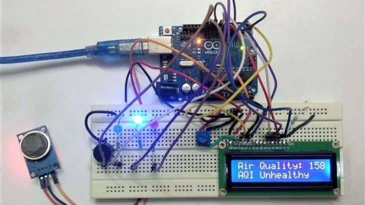
In this tutorial, I will provide the essential details about the air quality index, the pinout of the MQ-135 sensor, and how to measure air pollution using the MQ-135 sensor.
After this tutorial, you will be able to develop the air pollution monitoring and alert system using the Arduino Uno board with an MQ-135 sensor.
Hardware components
Makerguides.com is a participant in the Amazon Services LLC Associates Program, an affiliate advertising program designed to provide a means for sites to earn advertising fees by advertising and linking to products on Amazon.com.
What is air pollution?
Air pollution is the presence of excessive amounts of undesirable and unsafe solid or gaseous substances such as Carbon Monoxide, Lead, Nitrogen Oxide, Ozone, Particulate Matter, Sulfur Dioxide, etc., atmosphere.
Air pollution cause and effect
Air pollution has become an increasingly hazardous problem over the past few years. This factor is directly related to human health.
Global warming has become a severe concern for many countries; one widely faced issue is air pollution.
Other effects of air pollution also include various diseases like lung cancer, ischemic heart disease, asthma attacks, etc.
What is an air pollution monitoring system?
The Air pollution monitoring system is a facility to measure air pollutants using sensors, processing using microcontrollers, and showing results using various displays.
How can air pollution be monitored?
Air quality is a measure of how clean or polluted the air is. Air pollution is usually measured as Air Quality Index (AQI) in the PPM unit.
The sensors are most suitable for identifying hotspots at roadsides and near point sources. This sensor gets data that can be continuously monitored via different displays.
Air Quality Index: Source
What sensor can detect air pollution?
Nowadays, progress in electronics parts and availability of various sensors like MQ-135, MQ-2, MQ-3, MQ-4, MQ-5, MQ-6, etc., to measure the air pollutant, different systems are developed to monitor the number of air pollutants in the air.
MQ135 is one of the most popular sensors for measuring AQI in PPM.
What is the MQ-135 sensor?
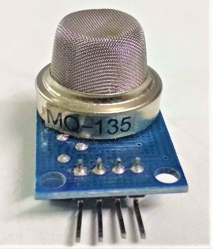
MQ-135 is a gas sensor that has lower conductivity in clean air. It is low cost and suitable for different applications.
This module operates at 5V , has 33Ω±5% resistance, and consumes around 150mA .
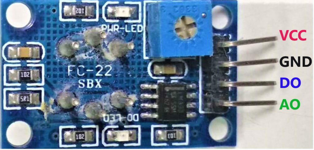
This sensor has four pins from four pins, Digital and Analog output pins, which are used to approximate these gasses levels in the atmosphere.
When these gasses go beyond a threshold limit in the air, the digital pin rises.
This threshold value can be set by using the onboard potentiometer.
Features of MQ-135 Sensor
- Wide detecting scope, Fast response, and High sensitivity
- Long lifespan
- Heater Voltage: 5.0V
- It contains analog output and high/low digital output
- The TTL output signal is a low level
- The operating Voltage is +5V
- Detected/Measure NH3, NOx, alcohol, Benzene, smoke, CO2, etc.
- Detection Range: 10 – 300 ppm NH3, 10 – 1000 ppm Benzene, 10 – 300 Alcohol
If you want more details about the MQ-135 sensor, refer to the MQ-135 datasheet and MQ-135 Schematic pdf .
Working Mechanism
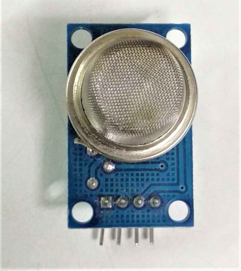
Now, let’s understand the working mechanism of the MQ-135 gas sensor.
The MQ-135 Gas sensor consists of Tin Dioxide (SnO2). When target pollution gas exists, the sensor’s conductivity increases along with the gas concentration.
Users can convert the change of conductivity to correspond to the output signal of gas concentration through a simple circuit.
The MQ-135 gas sensor has a high sensitivity to NH3, S2, C6H6 series steam and can monitor smoke and other toxic gasses. It can detect kinds of toxic gasses.
Pinout of MQ135
The MQ-135 sensor module has four pins, with the most important part being an adjustable potentiometer.
Can air quality be measured with an Arduino device?
Arduino Uno consists of 14 digital input/output (I/O) pins and 6 analog input pins, which fulfill the requirement of the AQI monitoring system.
This system could be extended by various modules compatible with Arduino, such as Ethernet shield, GSM/GPRS shield, GPS logger shield, RTC shield, and built-in board with VCC, Ground, etc.
Now you know quite a bit about the MQ-135 sensor, let’s move ahead and learn how to interface the MQ-135 with Arduino.
Wiring MQ-135 sensor with Arduino UNO
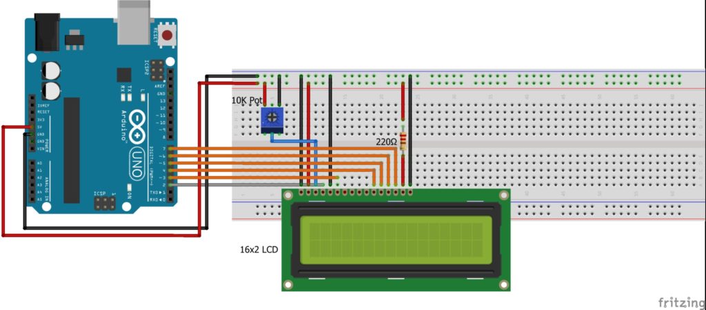
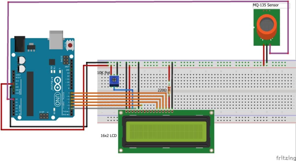
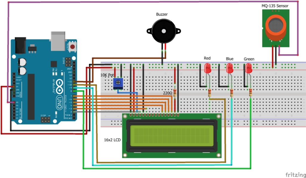
This circuit diagram is self-explanatory. The best way to interface this circuit is to start with an Arduino Uno board and LCD with the breadboard.
Step 1: First, place a 16×2 LCD on the breadboard, as shown in the figure.
Now, connect A to +5V with a 220-ohm resistor and K to Ground.
To vary the contrast of a 16×2 LCD, connect the VO to the middle pin of the potentiometer and VDD to +5V, VSS & RW to Ground.
Also, provide +5V and Ground to the potentiometer as depicted in the figure.
The summary of connections is mentioned in the below table.
Step 2: The MQ-135 module connects to the A0 pin of an Arduino Uno and connects GND to Ground, providing +5V to VCC.
Step 3: Connect Anode (+) of Green LED to digital pin 8 of Arduino; Blue LED to digital 9 pin of Arduino and Red LED to digital pin 10 of Arduino and all LEDs Cathode (-) Ground with 220-ohm resistor.
Step 4: Connect the buzzer’s positive terminal to digital pin 11 of Arduino and the negative terminal to the ground.
Arduino Code For Air Pollution Monitoring
The following code allows you to measure the air pollutant in the air in a PPM unit using the MQ-135 sensor.
You can see the results on a serial monitor and a 16×2 LCD.
How The Code Works
I have used an Arduino IDE to program an Arduino Uno board.
Step 1: First, I have included the necessary header file for 16×2 LCD,
Step 2: Define the variables for different pins used in the Arduino board for LCD, Buzzer, LED, and MQ-135. Also, define the variable for analog value.
Step 3: In the void setup() function, I have initialized the Buzzer, LED as an output device, and MQ-135 as an input device to Arduino Uno.
lcd.begin(); function initialize 16×2 LCD, before initializing the 16×2 LCD you must clear.
Using lcd.clear(); function. Also, set the baud rate at 9600-speed rate using Serial.begin(); function.
Step 4: After Initialize,16×2 LCD in set the cursor home position.
lcd.setCursor(0, 0);
The below message will print on the serial terminal and 16×2 LCD.
Serial.println(“AQI Alert System”);
lcd.print(“AQI Alert System”);
Step 5: In void loop() function, initializing the variable to catch up analog value, using analogRead(); function. And print on message serial terminal and 16×2 LCD.
Step 6: If the Suppose Analog value is between 0 to 50, the green LED will blink. Print on message serial terminal. And on LCD will print a message in the second row and first position.
Step 7: Same as, depending on AQI value, LED will blink and print on the message serial terminal and the 16×2 LCD following the table.
LCD Output:
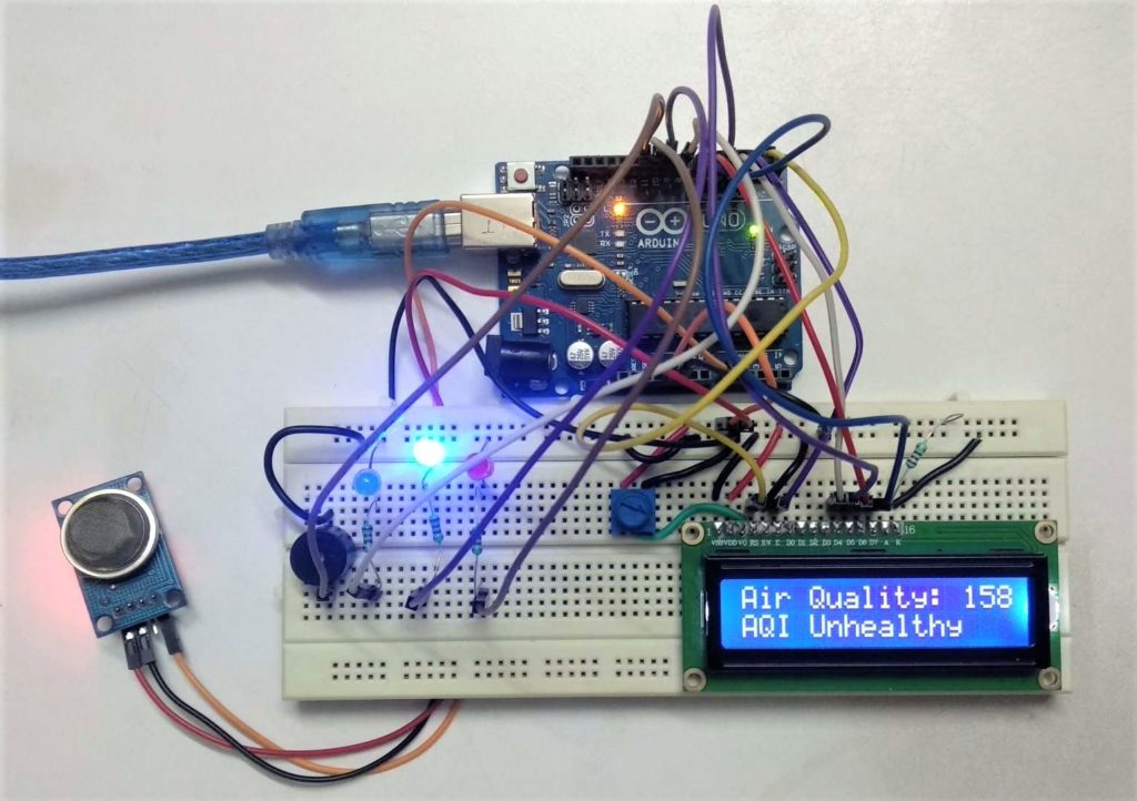
Serial Monitor Output:
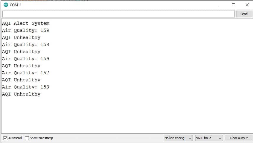
After this tutorial, you can develop your own Air Monitoring and Alert System using the MQ-135 sensor and Arduino Uno board.
I hope you found this tutorial informative. If you did, please share it with a friend who likes electronics and making things!
I would love to know what project you plan on building or have already made with the Arduino.
If you have any questions or suggestions or think things are missing in this tutorial, please leave a comment below.

Hiren is a professional Embedded Engineer with a Master’s Degree in Electronics and Communication Engineering. He is proficient in C and C++ and enjoys building DIY projects on Arduino, ESP32, PIC32, STM32 & Raspberry PI boards.
Shelke Snehal
Saturday 9th of March 2024
Thank you so much
Saturday 19th of August 2023
This code is terrible! Can't do "copy paste"!
hmm, works for me. I clicked "copy to clipboard" in the right upper corner and the copy worked. What Browser are you using? I am on Chrome.
Chackochan Sebastian
Thursday 1st of June 2023
Is there a need to calibrate the mq135 sensor for this project? If yes, can you tell me how?
Thursday 26th of January 2023
Hello there! I simply wish to give you a huge thumbs up for the great info you have got right here on this post "성인망가"Does running a blog like this take a large attention-grabbing discussion is worth comment. It’s difficult to find knowledgeable people using the same blog platform.
Embed the widget on your own site
In this tutorial, make an arduino based IOT project for air pollution monitoring using ThingSpeak platform.

Arduino Based Air Quality Monitoring IOT Project
- Circuit Connections -
- How the circuit works -
- Programming Guide -
- Comments (3)

Air pollution has become a common phenomenon everywhere. Specially in the urban areas, air pollution is a real-life problem. A lot of people get sick only due to air pollution. In the urban areas, the increased number of petrol and diesel vehicles and the presence of industrial areas at the outskirts of the major cities are the main causes of air pollution. The problem is seriously intensified in the metropolitan cities. Also, the climate change is now apparent. The governments all around the world are taking every measure in their capacity. Many European countries have aimed to replace petrol and diesel vehicles with the electric vehicles by 2030. Even India has aimed to do so by 2025. The use of coal for electricity generation is now going to be a thing of past. The nations are now focusing to generate energy from nuclear reactors and the renewable resources like solar energy, wind energy and hydroelectric power.
It is now important to monitor air pollution in real time in most of the urban areas. This project is aimed at developing an IOT device which can monitor air pollution in real time and log data to a remote server. Remote monitoring was facilitated using classical motes in the past, which has some pitfalls like limited memory, processing speed and complex programming strategies. By using Internet of Things and recording sensor data to a remote server, the limitations of memory in the monitoring devices and manual collection of data from the installed devices can be overcome. The IOT also helps monitoring the data in real time.
The air pollution monitoring device developed in this project is based Arduino UNO. The Arduino board connects with ThingSpeak platform using ESP8266 Wi-Fi Module. As the cities usually have Wi-Fi hotspots at most of the places, so the device can be easily installed near any hotspot for its operation. The ThingSpeak is a popular IOT platform which is easy to use and program. The sensor used for monitoring the air pollution is MQ-135 gas sensor. The sensor data is also displayed on a character LCD interfaced in the monitoring IOT device.
The sensing of data and sending it to the ThingSpeak server using Wi-Fi module is managed by the Arduino Sketch. The Arduino sketch is written, compiled and loaded to the Arduino board using Arduino IDE.
Circuit Connections -
The air pollution monitoring device is built by assembling the following components -
Arduino based Real Time Air Pollution Monitoring IOT device Circuit Connections
Arduino UNO - Arduino UNO is one of the most popular prototyping boards. It is small in size and packed with rich features. The board comes with built-in Arduino boot loader. It is an Atmega 328 based controller board which has 14 GPIO pins, 6 PWM pins, 6 Analog inputs and on board UART, SPI and TWI interfaces. In this IOT device, 9 pins of the board are utilized. There are six pins used to interface the character LCD. There are two pins utilized to interface the ESP8266 Wi-Fi Module and an analog input pin is used to connect with the MQ-135 sensor. Learn more about Arduino UNO from ]]> here. ]]>
16X2 Character LCD - The 16X2 LCD display is used to monitor the sensor values read by the Arduino board from MQ-135. It is interfaced with the Arduino UNO by connecting its data pins D4 to D7 with pins 6 down to 3 of the controller respectively. The RS and E pins of the LCD are connected to pins 13 and 12 of the controller respectively. The RW pin of the LCD module is connected to the ground. The circuit connections of the character LCD with the Arduino board are summarized in the following table -
ESP8266 Wi-Fi Module - The ESP8266 Wi-Fi Module is used to connect with any available internet hotspot and transfer sensor data to ThingSpeak Platform via Wi-Fi. The ESP8266 Wi-Fi Module is a self contained SOC with integrated TCP/IP protocol stack that can give any microcontroller access to a Wi-Fi network.
The ESP8266 is capable of either hosting an application or off loading all Wi-Fi networking functions from another application processor. Each ESP8266 module comes pre-programmed with an AT command set firmware. So, one can simply hook this up to an Arduino device. Here it uploads the monitoring data to the cloud. The module comes available in two models - ESP-01 and ESP-12. ESP-12 has 16 pins available for interfacing while ESP-01 has only 8 pins available for use. The ESP-12 has the following pin configuration -
The ESP-12 model is used in the project. The Reset and VCC pins of the module are connected to the 5V DC while Ground pin is connected to the common ground. The Tx and Rx pins of the module are connected to the pins 10 and 11 of the Arduino board respectively. The Arduino pins 10 and 11 are configured to serial receiver and transmitter through software serial function.
MQ-135 Sensor - MQ-135 is a gas sensor which is used to measure the concentration of combustible gases. It has lower conductivity in clean air while its conductivity increases with the presence of the combustible gases in the air. The sensor is highly sensitive to gases like Ammonia, Sulphide and Benzene steam. The sensor can detect the concentration of combustible gases in range from 100 PPM to 1000 PPM.
Sensitivity Curve of MQ-135 Sensor
From the sensitivity curve of the sensor, it can be seen that the resistance of the sensor decreases as the concentration of the target gas is increased in PPM while for clean air its resistance remains constant. In the graph, the Rs is the resistance in target gas and Ro is the resistance in clean air. The graph is shown for Carbon dioxide, Carbon Monoxide and Ammonia. The sensitivity of this sensor can be adjusted and calibrated to detect specific concentration level of a target gas. The sensor has four terminals - Ground, VCC, Digital Out and Analog Out. The VCC and Ground terminals of the sensor are connected to the common VCC and Ground. The Analog Output pin of the sensor is connected to the A0 pin of the Arduino. The analog output voltage from the sensor can be assumed directly proportional to the concentration of CO2 gas in PPM under standard conditions. The analog voltage is sensed from the sensor and converted to a digital value in range from 0 to 1023 by the inbuilt ADC channel of the controller. The digitized value is hence equal to the gas concentration in PPM.
Power Supply - The Arduino board and the Wi-Fi module require 3.3 V while LCD and MQ-135 sensor need 5V DC for their operation. The Arduino can be powered by connecting it to a USB connection. Since the voltage supply and ground pins of the other modules are connected with the common VCC and ground respectively, the rest of the components draw power from the 5V output of the Arduino board itself.
How the circuit works -
The device developed in this project can be installed near any Wi-Fi hotspot in a populated urban area. As the device is powered, the Arduino board loads the required libraries, flashes some initial messages on the LCD screen and start sensing data from the MQ-135 sensor. The sensitivity curve of the sensor for different combustible gases is already mentioned above. The sensor can be calibrated so that its analog output voltage is proportional to the concentration of polluting gases in PPM. The analog voltage sensed at the pin A0 of the Arduino is converted to a digital value by using the in-built ADC channel of the Arduino. The Arduino board has 10-bit ADC channels, so the digitized value ranges from 0 to 1023. The digitized value can be assumed proportional to the concentration of gases in PPM. The read value is first displayed on LCD screen and passed to the ESP8266 module wrapped in proper string through virtual serial function. The Wi-Fi module is configured to connect with the ThingSpeak IOT platform. ThingSpeak is an IOT analytics platform service that allows to aggregate, visualize and analyze live data streams in the cloud. ThingSpeak provides instant visualizations of data posted by the IOT devices to ThingSpeak server. With the ability to execute MATLAB code in ThingSpeak one can perform online analysis and processing of the data as it comes in.
The Wi-Fi module can be connected with the ThingSpeak server by sending AT commands from the module. The module first test the AT startup by sending the following command -
The command is passed by the controller to the Wi-Fi module using software serial function. In response to the command 'AT', the platform must respond with 'OK' if the cloud service is running. Then, the AT command to view the version information is passed as follow -
In response to this command, the IOT platform must respond by sending back the version information, sdk version and the time bin is compiled. Next, the AT command to set the connection to Wi-Fi mode is sent as follow -
AT + CWMODE = 3
By setting the parameter in CWMODE to 3, the Wi-Fi connection is configured to SoftAP as well as station mode. This AT command can in fact take three parameters as follow -
1 - set Wi-Fi connection to station mode
2 - set Wi-Fi connection to SoftAP mode
3 - set Wi-Fi connection to SoftAP + station mode
In response to this command, the IOT platform must send back the string indication the Wi-Fi connection mode set. Now the AT command to reset the module is sent as follow -
In response to this command, the Wi-Fi module must restart and send back a response of 'OK'. After resetting the module, AT command to setup multiple connections is enabled by sending the following command -
AT + CIPMUX=1
This AT command can take two parameters - 0 for setting single connection and 1 for setting multiple connections. Next, the command to connect with the Access Point (AP) is passed which takes two parameters where first parameter is the SSID of the registered cloud service on ThingSpeak and the other parameter is the password to login the cloud service.
AT+CWJAP=\"EngineersGarage\", \"egP@$$w0rd?\
Now, the AT command to get local IP address is passed as follow -
In response to this command, the local IP address of the Wi-Fi connection is sent back by the module. Now, the module is ready to establish TCP IP connection with the ThingSpeak server. The controller reads the sensor data and store it in a string variable. The TCP IP connection is established by sending the following AT command -
AT + CIPSTART = 4, "TCP", "184.106.153.149", 80
The AT + CIPSTART command can be used to establish a TCP connection, register an UDP port or establish an SSL connection. In the above command, it is used to establish a TCP IP connection. For establishing a TCP-IP connection, the command takes four parameters where first parameter is link ID which can be a number between 0 to 4, second parameter is connection type which can be TCP or UDP, third parameter is remote IP address or IP address of the cloud service to connect with and last parameter is detection time interval for checking if the connection is live. If the last parameter is set to 0, the TCP keep-alive feature is disabled otherwise a time interval in seconds range from 1 to 7200 can be passed as parameter. In response to this command, the server must respond with 'OK' if connection is successfully established otherwise it should respond with message 'ERROR'.
Now when the connection with the server is successfully established and the controller has read the sensor value, it can send the data to the cloud using the following command -
AT + CIPSEND = 4
This command takes four parameters, where first parameter is the link ID which can be a number between 0 to 4, second parameter is data length which can be maximum 2048 bytes long, third parameter is remote IP in case of an UDP connection and remote port number in case of UDP connection. The third and fourth parameter are optional and used only in case of UDP connection with the server. Since, the TCP IP connection is established, these parameters are not used. The command is followed by a string containing the URL having the field names and values passed through the HTTP GET method. In this project, a string containing the URL having API Key and the sensor value as the field and value is passed. The passed field and its value are logged on the cloud server. It is important to pass the API key in this URL as one of the field-value in order to connect with the registered cloud service. The Air quality measured by sensor can now be monitored and recorded through the thingspeak IOT plat form through the Wi-Fi module. The recorded data is shown at the ThingSpeak platform as follow -
User Interface of ThingSpeak Platform
The user needs to login the ThingSpeak platform from the registered account to view and monitor the sensor data. The Arduino sketch manages to read sensor data and send the AT commands for connecting with the IOT platform. Get an understanding of the Arduino code from the programming guide.
Programming Guide -
The program code is intended to be loaded on an Arduino UNO. In the program code, first the standard open-source libraries of Arduino for interfacing LCD and setting up virtual serial communication are imported. The softwareSerial library is imported for serial communication with the Wi-Fi module. This followed by declaration of variables representing the circuit connections of the Arduino with the character LCD, MQ-135 sensor and Wi-Fi module. The API key is stored in a variable and objects of LCD and virtual serial type are instantiated.
The setup() function is called in which baud rate for the serial communication with Wi-Fi module and serial data transmission to the LCD module is set to 9600. The LCD is initialized using begin() method and some flash messages are flashed on it. The WiFi mode and network connectivity is established using the AT commands with some delays. The delay should be given according to time it takes to connect with the network.
The loop() function is called in which the sensor value is read using the analogRead() function and the value is stored in a variable. The user-defined esp8266() function is called for transmitting the sensor data to the cloud.
In the esp8266() function, the AT command for establishing TCP connection is passed, and then API key of the ThingSpeak server is transmitted along with the sensor data in the form of an URL string. At an interval of every 16 seconds, the data gets updated to the ThingSpeak channel.
The loop function iterates infinitely sending the sensor data to the cloud in real time. This completes the Arduino sketch for Arduino based IOT Air Quality Monitoring IOT Project. Check out the complete code from the code section.
Source Code
Air Quality Montoring System using Arduino
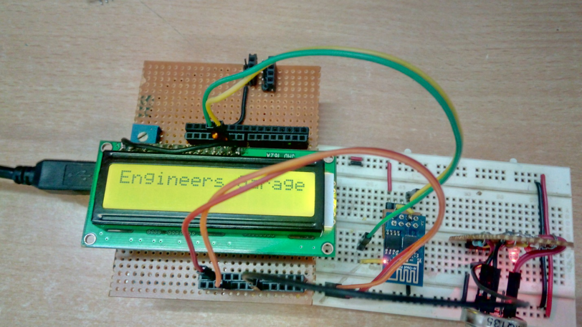
Code snippet #1
Code for air quality monitoring system.

TechnicalEngineer
Related channels and tags.


Air Pollution Detector
This device is intended to provide the user with a cost-efficient means of determining air quality. Our sensor focuses on the five components of the Environmental Protection Agency's Air Quality Index: ozone, particulate matter, carbon monoxide, sulfur dioxide, and nitrous oxide. This device detects all of these pollutants except sulfur dioxide. The device also includes a town gas sensor to alert the user to gas leaks or the presence of flammable gases. Furthermore, a temperature and humidity sensor is included as these conditions can impact the performance of the gas sensors.
We have yet to fully calibrate our device, but we have extracted data from sensor data sheets to make some preliminary estimations. The sensors used are relatively inexpensive and vary greatly from component to component so they need to be calibrated with known concentrations of the target gasses. We have not yet had the opportunity do so.

Step 1: Materials
Control and Power
- Arduino Uno
- 5V power supply
- RGB 16×2 LCD shield

- Shinyei PPD42 Particulate Matter Detector
- MQ-2 Gas Sensor
- MQ-9 Gas Sensor
- MiCS-2714 Gas Sensor (NO2)
- MiSC-2614 Gas Sensor (Ozone)
- Keyes DHT11 Temperature and Humidity Sensor
Box and Assembly
- Access to 3D printer
- Solder Board
- 10 to 15 wires of gauge 24
Step 2: Overall Circuit Diagram
The circuit diagram above is the entirety of this pollution detector works. A detailed circuit diagram for the solder board follows later. Note that you can change most of the digital ports and analog ports that sensors enter should you need to do so (for any reason); this will only require that you edit the code we have provided to account for these changes.

Step 3: Particulate Matter Sensor
We use two Shinyei PPD42 Dust Sensors to collect data about particulate matter.

Each Shinyei Detector has two signal outputs: one for small particulate matter (left yellow wire in the picture above) and one for larger particulate matter. These output signals are connected the digital inputs of the Ardiuno. The detector needs to be powered by supplying +5V and ground to the ports on the detector. See the overall circuit diagram for details.
Each detector uses an infrared LED and a photodetector to measure scattering off of small airborne particulates. Internal circuitry turns the photodetector output into digital output signals. Generally the sensor outputs a +5V signal, when it detects particles is sends out a low-voltage pulse. The fraction of the time that the output signal is low or the “low-pulse occupancy percentage” is proportional to the concentration of particulate matter in the air.
A detailed reverse engineering analysis of the Shinyei PPD42 by Tracy Allen can be found at http://takingspace.org/wp-content/uploads/ShinyeiP…
Step 4: Gas Sensor Circuit Board

Above is the circuit diagram for the circuit board hosting the gas sensors and temperature/humidity sensor. Details about mounting each of the separate devices are in the following steps. Note that your circuit board can look different from ours physically. In fact, we recommend you print a circuit board for the surface mount devices instead of using a solder board. It should work just as well as long as you follow the circuit diagram.
Step 5: Ozone and NO2 sensors
We use surface-mount sensors MiCS-2614 and MiCS-2714 to detect Ozone and Nitrogen Dioxide respectively.

Both of these devises use an internal resistor as their sensing element. The sensing resistor is connected between the pins (G) and (K ) in the diagram above. Use an ohmmeter to check that you have found the right pins. The resistance should be on the order of 10-20 kΩ.
Both devices also have a heating element between pins (A) and (H). This heating element keeps the sensing element at the appropriate temperature. The resistance of the heating element is 50-60Ω.
Ideally these devices should be surface mounted onto a circuit board. However, in the absence of a circuit board printer it is still possible to carefully solder to the back of these devices using very low temperature solder and much care.
As shown in the solder board circuit diagram, we place the 82Ω resistor and the 131Ω resistor in series with the heating elements of the MiCS-2614 and MiCS-2714 units respectively. This ensure that the heating elements receive the proper level of power. If you don't have access to a 131Ω resistor (it is not a standard value) use a 120Ω resistor and a 12Ω resistor in series.
We place the sensing resistors in both devises in series with 22kΩ resistors to create a voltage divider. From the voltage at the output of the voltage divider we can calculate the sensing resistance.
Rsenor = 22kΩ * (5V / Vout – 1)
Air Pollution De
Step 6: MQ Toxic Gas Sensors
We used MQ-2 and MQ-9 gas sensors to measure toxic gasses including Propane, Butane, LPG and Carbon Monoxide.

The MQ-2 and MQ-9 are very similar to the MiCS detectors. They use a gas-sensitive resistor (SnO2) to detect concentrations of toxic gases and have an internal heating element to keep the sensor at the right temperature. The circuits we use for these devises are practically the same as the circuits for the MiCS sensors, except that we use a transistor rather than a resistor to regulate heater power in the MQ-9.
Refer to the solder board circuit diagram for mounting details. For the MQ-2 sensor, connect the pins marked A to the 5V power, connect the pin marked G to ground, and connect the pin marked S is connected to ground in series with a 47 kΩ resistor. For the MQ-9 gas sensor, connect the pin marked A to the transistor, the pin marked B to the 5 V power, the pin marked G to ground, and the pin marked S to ground in series with a 10 kΩ resistor.
Step 7: Temperature and Humidity Sensors

This sensor is provided because temperature and humidity play a role in the gas concentrations that our sensors detect. High humidity and temperature as well as dramatic changes in either would have detrimental effects on the accuracy of readings It is therefore helpful to be able to monitor these variables. Both temperature and humidity can be read from this single sensor. Oriented as it is in the photo above, the left pin is to be attached to power, the middle pin is the output signal, and the right pin is grounded. The output signal for this component goes to a digital port on the Arduino. Our code is set up such expecting the temperature signal in digital port 2. This can be changed to another digital port should you need to; simply alter the code in accordance to what port you have chosen. Refer to the solder board diagram to use this component.
Step 8: Power and Fan

If you look at the circuit diagram for the entire project, you will see that we need only one input voltage of 5 V. A common adaptor like the one shown above can be used to power the project. Furthermore, you will need a fan to ensure airflow through the box and prevent overheating. We used the fan above but any fan that uses 5 V and is of the appropriate size can be used.

Step 9: Container
While there are many ways to make an effective box, we chose to use an UP 3D printer for our box. We have attached the STL that we used for the final printing.

Step 10: Coding
The code for extracting raw data from the device is attached above. This code will print the sensor resistance values, Shinyei PPD42 low-pulse occupancy percentages, and temperature and humidity readings to the computer via the serial monitor. It will cycle through the raw data on LCD screen as well.
In order to make the code work you will first need to download the libraries for the LCD shield and temperature and humidity sensors. You will find the libraries at the following websites
LCD shield code: https://learn.adafruit.com/rgb-lcd-shield/using-th…
Temperature and humidity sensor code: https://github.com/adafruit/DHT-sensor-library
Step 11: Interpreting the Data
We are in the process of determining how to transform raw sensor values into meaningful outputs. Calibration against known pollution sources will eventually be necessary to ensure accuracy. In meantime we have used sensor data sheets and prior research to make approximations.
To estimate particulate matter concentrations we use information from a research paper by David Holstius. The paper correlates the Shinyei PPD42 dust sensor outputs with EPA measurements. The graphs in the appendix show best fit lines for the data. We used the graphs to approximate PM2.5 concentration in micrograms per cubic meter as:
PM2.5 = 5 + 5 * (small PM low-pulse occupancy percentage)
To estimate gas concentrations from MiCS gas sensors, we use the graphs in the datasheets ( NO2 and O3 ) to extract functions relating sensor resistance to gas concentration.
For MQ sensors we use the graphs on the device datasheets to qualitatively assess the data. When the resistance value drops to less than half of the resistance in air, it is likely that the devise is detecting the target gasses. When resistance drops by a factor of 10, the levels of target gas are likely around 1000 ppm, close to the legal safety limit.
Once we obtain approximate concentrations of the target gasses, we defer to US government standards to interpret the data. We primarily use the EPA Technical Assistance Document for the Reporting of Daily Air Quality and a CDC information sheet on the hazards of propane.
Unfortunately our code that interprets the raw data is not yet fully functional. We hope to be able upload it at a later date.
Source: Air Pollution Detector
About The Author
Ibrar Ayyub
I am an experienced technical writer holding a Master's degree in computer science from BZU Multan, Pakistan University. With a background spanning various industries, particularly in home automation and engineering, I have honed my skills in crafting clear and concise content. Proficient in leveraging infographics and diagrams, I strive to simplify complex concepts for readers. My strength lies in thorough research and presenting information in a structured and logical format.
Leave a Comment Cancel Reply
Your email address will not be published. Required fields are marked *
Privacy Overview

Electronics
Air pollution detector.
Air pollution consists of chemicals or particles in the atmosphere that causes serious health and environmental health but what causes air pollution for our planet. Most of the air pollution comes from human activities very least are from natural activities like a volcano eruption. Most of the harmful gases formed are carbon dioxide, carbon monoxide, sulfates, nitrates, through Greenhouse gases, smog, toxic pollutants like lead and mercury now the question is do we have a solution? In this project, you are going to make an air pollution detector by using an Arduino and some air quality sensors. You need one Arduino Uno, LCD display, and 5-volt power supply
Electronics Kit will be shipped to you and you can learn and build using tutorials. You can start for free today!
1. Wireless Communication (Career Building Course)
2. Animatronic Hand
3. Embedded Systems (Career Building Course)
4. Home Automation using IoT
5. Robotic Arm
6. Sensor Guided Robotics
7. Smart Energy Meter using GSM
8. Solar & Smart Energy Systems
9. Automatic Solar Tracker
10. GPS & GSM based Tracker
11. 5 Arduino Projects
12. Biometric Authentication
13. Access Control with RFID
14. Automated Railway Crossing
15. 4 Smart Energy Projects
16. PCB Manufacturing
17. Health Monitoring Wearable
18. Persistence of Vision
19. Smart Traffic Lighting System
20. Automation using PLC
Project Description:
- USB Module: Arduino Uno is the most popular Arduino board so far, however it is sometimes frustrating when your project requires a lot of sensors or LEDs and your jumper wires are in a mess. The purpose of creating the Grove – Base Shield is to help you get rid of breadboard and jumper wires. With the rich grove connectors on the breadboard, you can add all the grove modules to the Arduino Uno very conveniently!
- Dust sensor: This Dust Sensor gives a good indication of the air quality in an environment by measuring the dust concentration. The Particulate Matter level (PM level) in the air is measured by counting the Low Pulse Occupancy time (LPO time) in given time unit. LPO time is proportional to PM concentration. This sensor can provide reliable data for air purifier systems; it is responsive to PM of diameter 1?m.
Latest projects on Electronics
Want to develop practical skills on Electronics? Checkout our latest projects and start learning for free
- HCHO sensor: AThe Grove - HCHO Sensor is a semiconductor VOC gas sensor. It uses the VOC sensor WSP2110 whose conductivity changes with the concentration of VOC gas in air. With a circuit, the conductivity can be converted to an output signal that corresponds to the gas concentration. This sensor has a very high sensitivity and stability, it can detect the gas whose concentration is up to 1ppm. It can be used to detect Toluene, Methanal, Benzene, Alcohol, Acetone etc. This product can be used to detect the presence of harmful gas in the home environment. It can be a good assistant to improve indoor air quality.
- LCD Module for Arduino UNO: =The Liquid Crystal Library allows you to control LCD displays that are compatible with the Hitachi HD44780 driver. There are many of them out there, and you can usually tell them by the 16-pin interface.
Skyfi Labs helps students learn practical skills by building real-world projects.
You can enrol with friends and receive kits at your doorstep
You can learn from experts, build working projects, showcase skills to the world and grab the best jobs. Get started today!
- Ardinou ultra kit : = 1X Arduino Uno R3 1X Arduino & Breadboard Holder 1X Bread Board 1X Shift Register 2X P2N2222A Transistors 2X 1N4148 Diodes 1X DC Motor with wires 1X Small Servo 1X 5V Relay 1X TMP36 Temp Sensor 1X 6' USB Cable 65X Jumper Wires 1X Photocell 1X Tri-color LED 10X Red LED 10X yellow LED 1X 10K Trimpot 1X Piezo Buzzer 2X Big 12mm Buttons 45X 330 Resistors 45X 10K Resistors
- The sensor is designed for indoor air quality testing. The main gas detected is carbon monoxide, alcohol, acetone, thinner, formaldehyde and other slightly toxic gases.
- Dust sensor
- HCHO sensor
- LCD Module for Arduino UNO
- Air quality sensors
- Renewable Energy
Join 250,000+ students from 36+ countries & develop practical skills by building projects
Get kits shipped in 24 hours. Build using online tutorials.

More Project Ideas on Electronics
Subscribe to receive more project ideas.
Stay up-to-date and build projects on latest technologies
☎ Have a Query?
Suggestions or feedback?
MIT News | Massachusetts Institute of Technology
- Machine learning
- Social justice
- Black holes
- Classes and programs
Departments
- Aeronautics and Astronautics
- Brain and Cognitive Sciences
- Architecture
- Political Science
- Mechanical Engineering
Centers, Labs, & Programs
- Abdul Latif Jameel Poverty Action Lab (J-PAL)
- Picower Institute for Learning and Memory
- Lincoln Laboratory
- School of Architecture + Planning
- School of Engineering
- School of Humanities, Arts, and Social Sciences
- Sloan School of Management
- School of Science
- MIT Schwarzman College of Computing
Low-cost device can measure air pollution anywhere
Press contact :, media download.

*Terms of Use:
Images for download on the MIT News office website are made available to non-commercial entities, press and the general public under a Creative Commons Attribution Non-Commercial No Derivatives license . You may not alter the images provided, other than to crop them to size. A credit line must be used when reproducing images; if one is not provided below, credit the images to "MIT."
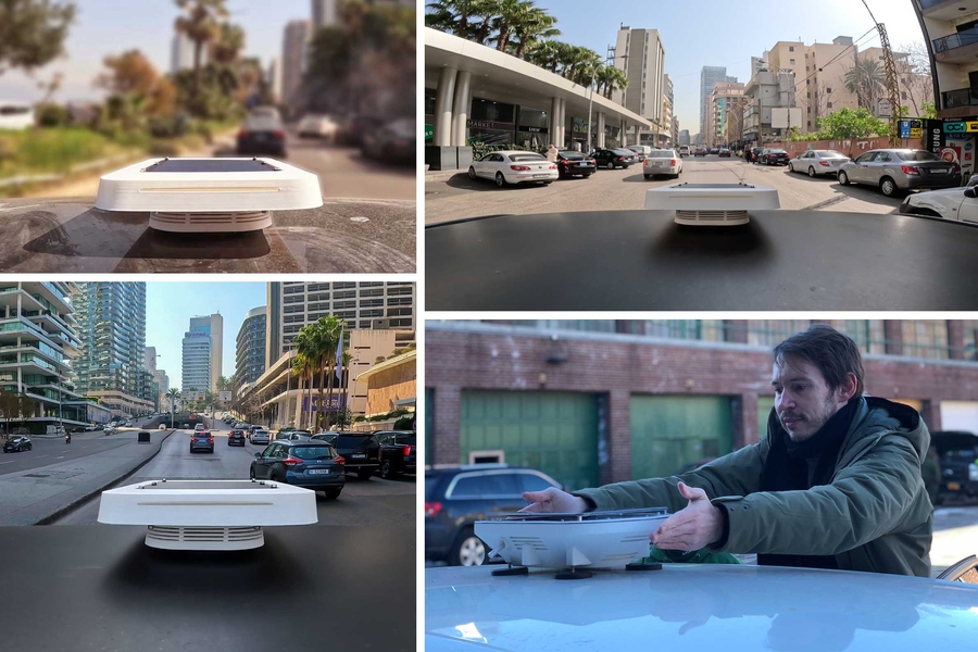
Previous image Next image
Air pollution is a major public health problem: The World Health Organization has estimated that it leads to over 4 million premature deaths worldwide annually. Still, it is not always extensively measured. But now an MIT research team is rolling out an open-source version of a low-cost, mobile pollution detector that could enable people to track air quality more widely.
The detector, called Flatburn, can be made by 3D printing or by ordering inexpensive parts. The researchers have now tested and calibrated it in relation to existing state-of-the-art machines, and are publicly releasing all the information about it — how to build it, use it, and interpret the data.
“The goal is for community groups or individual citizens anywhere to be able to measure local air pollution, identify its sources, and, ideally, create feedback loops with officials and stakeholders to create cleaner conditions,” says Carlo Ratti, director of MIT’s Senseable City Lab.
“We’ve been doing several pilots around the world, and we have refined a set of prototypes, with hardware, software, and protocols, to make sure the data we collect are robust from an environmental science point of view,” says Simone Mora, a research scientist at Senseable City Lab and co-author of a newly published paper detailing the scanner’s testing process. The Flatburn device is part of a larger project, known as City Scanner, using mobile devices to better understand urban life.
“Hopefully with the release of the open-source Flatburn we can get grassroots groups, as well as communities in less developed countries, to follow our approach and build and share knowledge,” says An Wang, a researcher at Senseable City Lab and another of the paper’s co-authors.
The paper, “ Leveraging Machine Learning Algorithms to Advance Low-Cost Air Sensor Calibration in Stationary and Mobile Settings ,” appears in the journal Atmospheric Environment .
In addition to Wang, Mora, and Ratti the study’s authors are: Yuki Machida, a former research fellow at Senseable City Lab; Priyanka deSouza, an assistant professor of urban and regional planning at the University of Colorado at Denver; Tiffany Duhl, a researcher with the Massachusetts Department of Environmental Protection and a Tufts University research associate at the time of the project; Neelakshi Hudda, a research assistant professor at Tufts University; John L. Durant, a professor of civil and environmental engineering at Tufts University; and Fabio Duarte, principal research scientist at Senseable City Lab.
The Flatburn concept at Senseable City Lab dates back to about 2017, when MIT researchers began prototyping a mobile pollution detector, originally to be deployed on garbage trucks in Cambridge, Massachusetts. The detectors are battery-powered and rechargable, either from power sources or a solar panel, with data stored on a card in the device that can be accessed remotely.
The current extension of that project involved testing the devices in New York City and the Boston area, by seeing how they performed in comparison to already-working pollution detection systems. In New York, the researchers used 5 detectors to collect 1.6 million data points over four weeks in 2021, working with state officials to compare the results. In Boston, the team used mobile sensors, evaluating the Flatburn devices against a state-of-the-art system deployed by Tufts University along with a state agency.
In both cases, the detectors were set up to measure concentrations of fine particulate matter as well as nitrogen dioxide, over an area of about 10 meters. Fine particular matter refers to tiny particles often associated with burning matter, from power plants, internal combustion engines in autos and fires, and more.
The research team found that the mobile detectors estimated somewhat lower concentrations of fine particulate matter than the devices already in use, but with a strong enough correlation so that, with adjustments for weather conditions and other factors, the Flatburn devices can produce reliable results.
“After following their deployment for a few months we can confidently say our low-cost monitors should behave the same way [as standard detectors],” Wang says. “We have a big vision, but we still have to make sure the data we collect is valid and can be used for regulatory and policy purposes,”
Duarte adds: “If you follow these procedures with low-cost sensors you can still acquire good enough data to go back to [environmental] agencies with it, and say, ‘Let’s talk.’”
The researchers did find that using the units in a mobile setting — on top of automobiles — means they will currently have an operating life of six months. They also identified a series of potential issues that people will have to deal with when using the Flatburn detectors generally. These include what the research team calls “drift,” the gradual changing of the detector’s readings over time, as well as “aging,” the more fundamental deterioration in a unit’s physical condition.
Still, the researchers believe the units will function well, and they are providing complete instructions in their release of Flatburn as an open-source tool. That even includes guidance for working with officials, communities, and stakeholders to process the results and attempt to shape action.
“It’s very important to engage with communities, to allow them to reflect on sources of pollution,” says Mora.
“The original idea of the project was to democratize environmental data, and that’s still the goal,” Duarte adds. “We want people to have the skills to analyze the data and engage with communities and officials.”
Share this news article on:
Press mentions, fast company.
MIT researchers have developed a low-cost air quality sensor that can be 3-D printed using open-source instructions and used by people around the world, reports Kristin Toussaint for Fast Company. “The reason we started this project was because we wanted to democratize environmental data,” explains research scientist Simone Mora. “We’re not just opening the data we’ve collected so far, but we hope to funnel a huge development in terms of sensors deployed in the streets, and in turn [make] the data collected available to everyone.”
Previous item Next item
Related Links
- Senseable City Lab
- Department of Urban Studies and Planning
- School of Architecture and Planning
Related Topics
- Urban studies and planning
- Cambridge, Boston and region
Related Articles

Augmented reality headset enables users to see hidden objects

Where do stolen bikes go?

Can your phone tell if a bridge is in good shape?
New programmable materials can sense their own movements

Taking a city’s pulse with moveable sensors
More mit news.

Has remote work changed how people travel in the U.S?
Read full story →

Physicist Netta Engelhardt is searching black holes for universal truths

MIT community members gather on campus to witness 93 percent totality

Extracting hydrogen from rocks

When an antibiotic fails: MIT scientists are using AI to target “sleeper” bacteria
MIT engineers design flexible “skeletons” for soft, muscle-powered robots
- More news on MIT News homepage →
Massachusetts Institute of Technology 77 Massachusetts Avenue, Cambridge, MA, USA
- Map (opens in new window)
- Events (opens in new window)
- People (opens in new window)
- Careers (opens in new window)
- Accessibility
- Social Media Hub
- MIT on Facebook
- MIT on YouTube
- MIT on Instagram
Continue to site >>>

About | Contact | Advertise
- Microcontroller Based Projects
ESP8266 based Air Pollution Detector

India has the distinction of releasing the largest volumes of pollutants into the air after China. The majority of the cities with the most polluted air are in India. Air pollution is the fifth largest killer in the country, according to Global Burden of Disease. Many areas in the Indian States, and the world, are faced with serious air quality problems. It is the most important environmental health risk of our times. Air in our cities is becoming hazardous to breathe but it is not immediately reported to the controlling authorities. Currently, Air in our cities is becoming hazardous to breathe but it is not immediately reported to the controlling authorities and therefore result in a delay in action. Because of this the polluting agencies like the factories are getting escaped, resulting in hazardous health issues. So to cater this problem, I have developed an Air pollution detector using ESP8266 . This system detects and reports pollution on the mobile app developed by me. It also gives warnings to the nearby public when the pollution crosses the defined limit by turning on the siren.

Previously, we built some projects on Air Quality Monitoring,
- Air Pollution Monitoring System using Arduino
- TVOC and CO2 Measurement using Arduino
- Air Quality Analyzer using Arduino
- Air Quality Index Monitoring System using ESP32
Component Required for Air Pollution Detector
Project Used Hardware
- Wemos D1 (esp8266),
- MQ3 Sensor,
- Battery \ solar panel \ 5-12v adapter for power supply,
Project Used Software
- Kodular Creator (clone of MIT app inventor),
- Arduino IDE,
- Firebase Realtime Database,
- Firebase Authentication
Project Hardware/Software Selection
On the Hardware side, I used Wemos D1 which is an esp8266 based board because it is a low-cost microcontroller that has Wi-Fi connectivity for sending data to the internet. I have also used an MQ3 sensor for measuring the amount of smoke present in the air, Buzzer as a siren, and a power supply for the device. On the Software side, I have used Arduino IDE to program the microcontroller. As a database and IoT server, I have used Google Firebase's Realtime Database. To build the android app I have used Kodular Creator which is a clone of MIT app inventor. For Authentication, I have used Firebase Authentication.
Air Pollution Detector Circuit Diagram
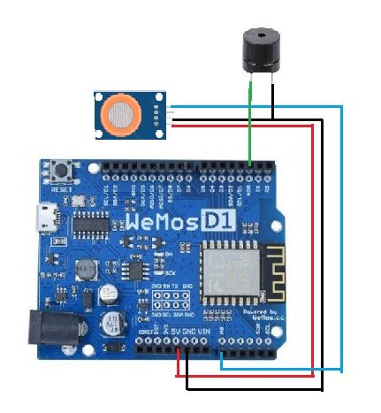
The GND and VCC of the MQ3 sensor are connected to GND and 5v of the Wemos D1 Respectively. The Analog output is connected to the A0 pin of the Wemos D1. The Buzzer is connected to the D2 pin of the Wemos D1 controller.
Ask Our Community Members

- Log in or register to post comments

Join 100K+ Subscribers
Your email is safe with us, we don’t spam.
Be a part of our ever growing community.
Copyright © 2023 Circuit Digest . All rights reserved.
Low-cost device can measure air pollution anywhere
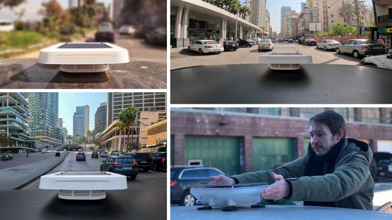
Air pollution is a major public health problem: The World Health Organization has estimated that it leads to over 4 million premature deaths worldwide annually. Still, it is not always extensively measured. But now an MIT research team is rolling out an open-source version of a low-cost, mobile pollution detector that could enable people to track air quality more widely.
The detector, called Flatburn, can be made by 3D printing or by ordering inexpensive parts. The researchers have now tested and calibrated it in relation to existing state-of-the-art machines, and are publicly releasing all the information about it — how to build it, use it, and interpret the data.
“The goal is for community groups or individual citizens anywhere to be able to measure local air pollution, identify its sources, and, ideally, create feedback loops with officials and stakeholders to create cleaner conditions,” says Carlo Ratti, director of MIT’s Senseable City Lab.
“We’ve been doing several pilots around the world, and we have refined a set of prototypes, with hardware, software, and protocols, to make sure the data we collect are robust from an environmental science point of view,” says Simone Mora, a research scientist at Senseable City Lab and co-author of a newly published paper detailing the scanner’s testing process. The Flatburn device is part of a larger project, known as City Scanner, using mobile devices to better understand urban life.
“Hopefully with the release of the open-source Flatburn we can get grassroots groups, as well as communities in less developed countries, to follow our approach and build and share knowledge,” says An Wang, a researcher at Senseable City Lab and another of the paper’s co-authors.
The paper, “ Leveraging Machine Learning Algorithms to Advance Low-Cost Air Sensor Calibration in Stationary and Mobile Settings ,” appears in the journal Atmospheric Environment .
In addition to Wang, Mora, and Ratti the study’s authors are: Yuki Machida, a former research fellow at Senseable City Lab; Priyanka deSouza, an assistant professor of urban and regional planning at the University of Colorado at Denver; Tiffany Duhl, a researcher with the Massachusetts Department of Environmental Protection and a Tufts University research associate at the time of the project; Neelakshi Hudda, a research assistant professor at Tufts University; John L. Durant, a professor of civil and environmental engineering at Tufts University; and Fabio Duarte, principal research scientist at Senseable City Lab.
The Flatburn concept at Senseable City Lab dates back to about 2017, when MIT researchers began prototyping a mobile pollution detector, originally to be deployed on garbage trucks in Cambridge, Massachusetts. The detectors are battery-powered and rechargable, either from power sources or a solar panel, with data stored on a card in the device that can be accessed remotely.
The current extension of that project involved testing the devices in New York City and the Boston area, by seeing how they performed in comparison to already-working pollution detection systems. In New York, the researchers used 5 detectors to collect 1.6 million data points over four weeks in 2021, working with state officials to compare the results. In Boston, the team used mobile sensors, evaluating the Flatburn devices against a state-of-the-art system deployed by Tufts University along with a state agency.
In both cases, the detectors were set up to measure concentrations of fine particulate matter as well as nitrogen dioxide, over an area of about 10 meters. Fine particular matter refers to tiny particles often associated with burning matter, from power plants, internal combustion engines in autos and fires, and more.
The research team found that the mobile detectors estimated somewhat lower concentrations of fine particulate matter than the devices already in use, but with a strong enough correlation so that, with adjustments for weather conditions and other factors, the Flatburn devices can produce reliable results.
“After following their deployment for a few months we can confidently say our low-cost monitors should behave the same way [as standard detectors],” Wang says. “We have a big vision, but we still have to make sure the data we collect is valid and can be used for regulatory and policy purposes,”
Duarte adds: “If you follow these procedures with low-cost sensors you can still acquire good enough data to go back to [environmental] agencies with it, and say, ‘Let’s talk.’”
The researchers did find that using the units in a mobile setting — on top of automobiles — means they will currently have an operating life of six months. They also identified a series of potential issues that people will have to deal with when using the Flatburn detectors generally. These include what the research team calls “drift,” the gradual changing of the detector’s readings over time, as well as “aging,” the more fundamental deterioration in a unit’s physical condition.
Still, the researchers believe the units will function well, and they are providing complete instructions in their release of Flatburn as an open-source tool. That even includes guidance for working with officials, communities, and stakeholders to process the results and attempt to shape action.
“It’s very important to engage with communities, to allow them to reflect on sources of pollution,” says Mora.
“The original idea of the project was to democratize environmental data, and that’s still the goal,” Duarte adds. “We want people to have the skills to analyze the data and engage with communities and officials.”

Related Posts
The heat is on: accelerating climate action at a time of record-breaking te....

Atmospheric observations in China show rise in emissions of a potent greenh...

TILclimate presents: What the heck is El Niño, anyway? (from Outside/In)

Probing the atmosphere, protecting the biosphere

MIT Climate News in Your Inbox
Search code, repositories, users, issues, pull requests...
Provide feedback.
We read every piece of feedback, and take your input very seriously.
Saved searches
Use saved searches to filter your results more quickly.
To see all available qualifiers, see our documentation .
air-pollution-prediction
Here are 8 public repositories matching this topic..., jyoti0225 / air-pollution-forecasting.
Time Series Analysis of Air Pollutants(PM2.5) using LSTM model
- Updated Aug 12, 2020
- Jupyter Notebook
zouguojian / Personal-Accepted-Research
Welcome to quote our published papers, and the codes have been uploaded.
- Updated Jan 30, 2024
SukonyaPhukan92 / Image_Based_Air_Pollution_detection_using_InceptionV3_Model
In this project work, the main motive is to build a deep learning model to detect air pollution from real-time images. In order to achieve that goal, we have collected data from different sources and then enhanced the low-quality images using the Image enhancement technique. Our next step was to train a CNN (Convolutional Neural Network) on the …
- Updated Oct 24, 2021
Afkerian / Beijing-Multi-Site-Air-Quality-Data-Data-Set
The present project aims to predict air pollution in Beijing, China, using the data set "Beijing Multi-Site Air-Quality Data Data Set"
- Updated Jul 1, 2023
khwajawisal / Time-series-analysis
Time series analysis to predict AQI in Delhi, dataset collated from Indian Meteorological department of India.
- Updated Oct 2, 2019
SharathHebbar / Air-pollution-prediction-
Air pollution prediction using linear regression
- Updated Nov 8, 2023
C22-PS340 / Routeco
Routeco - Your Route Comrade
- Updated Jun 13, 2022
JuliusFx131 / GeoAI-Challenge-for-Air-Pollution-Susceptibility-Mapping
This problem statement focused on building machine learning models that would assist create city-level air pollution susceptibility maps with a 5-meter spatial resolution for milan city in Italy. This city has unique challenges of dealing with pollution levels due to its unique topographic features.
- Updated Dec 4, 2023
Improve this page
Add a description, image, and links to the air-pollution-prediction topic page so that developers can more easily learn about it.
Curate this topic
Add this topic to your repo
To associate your repository with the air-pollution-prediction topic, visit your repo's landing page and select "manage topics."
A Smart Air Pollution Detector Using Machine Learning
Ieee account.
- Change Username/Password
- Update Address
Purchase Details
- Payment Options
- Order History
- View Purchased Documents
Profile Information
- Communications Preferences
- Profession and Education
- Technical Interests
- US & Canada: +1 800 678 4333
- Worldwide: +1 732 981 0060
- Contact & Support
- About IEEE Xplore
- Accessibility
- Terms of Use
- Nondiscrimination Policy
- Privacy & Opting Out of Cookies
A not-for-profit organization, IEEE is the world's largest technical professional organization dedicated to advancing technology for the benefit of humanity. © Copyright 2024 IEEE - All rights reserved. Use of this web site signifies your agreement to the terms and conditions.
Air Pollution Control Using IoT: A Survey
- Conference paper
- First Online: 15 March 2022
- Cite this conference paper

- Sunanda Dixit 18 ,
- S. Vasupradha 18 ,
- Sneha Vinayak Todurkar 18 ,
- K. S. Harshitha 18 &
- O. Alekhya 18
Part of the book series: Advances in Intelligent Systems and Computing ((AISC,volume 1415))
493 Accesses
1 Citations
One of the critical issues affecting today’s life is air pollution. Due to the increase in industrialization and concentration of poisonous gases in the environment, air around us has become highly toxic. These gases cause a plenty of respiratory and other diseases. A wide variety of sensors can be utilized to reduce and control the air pollution. The sensors that we use must be able to operate for long periods and withstand harsh conditions. The main aim of our project is to provide detection and analysis of various pollutants and gases in air using various IoT components such as sensors, microcontroller, and Wi-Fi-network module and then suggesting solutions to prevent air pollution.
- Internet of Things (IoT)
- Wi-Fi module
This is a preview of subscription content, log in via an institution to check access.
Access this chapter
- Available as PDF
- Read on any device
- Instant download
- Own it forever
- Available as EPUB and PDF
- Compact, lightweight edition
- Dispatched in 3 to 5 business days
- Free shipping worldwide - see info
Tax calculation will be finalised at checkout
Purchases are for personal use only
Institutional subscriptions
Jo JH, Jo BW, Kim JH, Kim SJ, Han WY (2020) Development of an IoT-based indoor air quality monitoring platform. J Sens. Article ID 8749764
Google Scholar
Ali AbaasAboodee Al-Zaheiree YATAZSGRK (2020) Advanced air pollution detection using IOT and raspberry PI. Int J Recent Technol Eng 8(5):5390–5394
Lücking M, Kannengießer N, Kilgus M, Riedel T, Beigl M, Sunyaev A, Stork W (2020) The merits of a decentralized pollution-monitoring system based on distributed ledger technology. IEEE Access 8:189365–189381
Article Google Scholar
Monika Singh MKPKC (2019) IoT based air pollution monitoring system using Arduino. Int Res J Eng Technol 6(8):534–537
Abba S, Patrick BE (2019) Smart framework for environmental pollution monitoring and control system. Sens Transducers 229(1):84–93
Shaheduzzaman Chowdhury MSIMKRMS (2019) Design and implementation of an IoT based air pollution detection and monitoring system. IEEE Access
Vijaya Kumar Sajjan PS (2019) Pollution monitoring using IoT. Procedia Comput Sci 155:710–715
Abdulrahman Abdullah Alkandari SM (2018) Implementation of monitoring system for air quality using raspberry PI: experimental study. Indonesian J Electr Eng Comput Sci 10(1):43–49
Arunkumar KAAMSD (2018) Smart air pollution detection and monitoring using Iot. Int J Pure Appl Math 119:935–941
Chandana B, Chandana K, Jayashree N, Anupama M, Vanamala CK (2018) Pollution monitoring using IoT and sensor technology. Int Res J Eng Technol 5(3):2932–2935
Okokpujie K, Noma-Osaghae E, Odusamy M, John S (2018) A smart air pollution monitoring system. Int J Civil Eng Technol 9(9):799–809
Benammar M, Abdaoui A, Ahmad S, Touati F, Kadri A (2018) A modular IoT platform for real-time indoor air quality monitoring. Sensors 18(2):581
Gagan Parmar SLMKC (2017) An IoT based low cost air pollution monitoring system. In: Proceeding international conference on recent innovations is signal processing and embedded systems, pp 524–528
Poonam Pal RGSTA (2017) IOT based air pollution monitoring system. ISO 9001:2008 Certified J 4(10):1137–1140
Balasubramaniyan C, Manivannan D (2016) Iot enabled air quality monitoring system (AQMS) using raspberry Pi. Indian J Sci Technol 9(39):1–6
Ramagiri Rushikesh CMRS (2015) Development of IoT based vehicular pollution monitoring system. In: International conference on green computing and internet of things (ICGCIoT), pp 779–783
Vallero DA (2015) Air pollution
Vashi D et al (2015) Air pollution and its control measures. Adv Appl Sci Res 6(5):118–121
Vaibhaw Garg DMPC (2013) Causes, consequences and control of air pollution. In: All India Seminar on Methodologies for Air Pollution Control
Movva Pavani PTR (2017) Urban air pollution monitoring using wireless. Int J CommunNetw Inform Secur (IJCNIS) 9(3):439–449
Mr. Mahendra Solanki M (2020) Separation of carbon from air by electrostatic 6(12)
Kulkarni A et al (2019) Retrofit electrostatic precipitator for automobiles 6(9)
Chowkwanyun M (2019) Two cheers for air pollution control: triumphs and limits of the mid-century fight for air quality. Publ Health Rep 134(3):307–312
Afshari A et al (2020) Electrostatic precipitators as an indoor air cleaner—a literature review. Sustainability 12(21):8774
Changa Y-S et al (2020) An LSTM-based aggregated model for air pollution forecasting. Elsevier, pp 1451–1463
Ayse Fidan Altun MK (2020) Utilization of electrostatic precipitators for healthy indoor. In: E3S web of conferences
Dixit S (2019) 3D reconstruction of 2D X-ray images. In: 4th international conference on computational systems and information technology for sustainable solution (CSITSS), pp 1–5
Karimunnisa Begum SD (2016) Industrial WSN using IoT: a survey. In: International conference on electrical, electronics, and optimization techniques (ICEEOT), pp 499–504
Mugunthan DTVSR (2019) Review on IoT based smart grid architecture. J Electr Eng Autom 1(1):12–20
Lai K-L et al (2021) Development of smart cities with fog. JUCCT 3(1):52–60
Meivel S et al (2021) Air pollution monitoring system using IOT and artificial intelligence. Int J Modern Agric 10(2):3085–3089
Download references
Author information
Authors and affiliations.
Computer Science and Engineering Department, BMS Institute of Technology and Management, Bangalore, India
Sunanda Dixit, S. Vasupradha, Sneha Vinayak Todurkar, K. S. Harshitha & O. Alekhya
You can also search for this author in PubMed Google Scholar
Corresponding author
Correspondence to Sunanda Dixit .
Editor information
Editors and affiliations.
Department of Computer Science Engineering, Vaigai College of Engineering, Madurai, Tamil Nadu, India
A. Pasumpon Pandian
Department of Business Administration, The Gerald Schwartz School of Business, Nova Scotia, NS, Canada
Ram Palanisamy
Department of Computer Science Engineering, Malla Reddy College of Engineering, Secunderabad, Telangana, India
M. Narayanan
University of the Ryukyus, Okinawa, Japan
Tomonobu Senjyu
Rights and permissions
Reprints and permissions
Copyright information
© 2022 The Author(s), under exclusive license to Springer Nature Singapore Pte Ltd.
About this paper
Cite this paper.
Dixit, S., Vasupradha, S., Todurkar, S.V., Harshitha, K.S., Alekhya, O. (2022). Air Pollution Control Using IoT: A Survey. In: Pandian, A.P., Palanisamy, R., Narayanan, M., Senjyu, T. (eds) Proceedings of Third International Conference on Intelligent Computing, Information and Control Systems. Advances in Intelligent Systems and Computing, vol 1415. Springer, Singapore. https://doi.org/10.1007/978-981-16-7330-6_45
Download citation
DOI : https://doi.org/10.1007/978-981-16-7330-6_45
Published : 15 March 2022
Publisher Name : Springer, Singapore
Print ISBN : 978-981-16-7329-0
Online ISBN : 978-981-16-7330-6
eBook Packages : Intelligent Technologies and Robotics Intelligent Technologies and Robotics (R0)
Share this paper
Anyone you share the following link with will be able to read this content:
Sorry, a shareable link is not currently available for this article.
Provided by the Springer Nature SharedIt content-sharing initiative
- Publish with us
Policies and ethics
- Find a journal
- Track your research

An official website of the United States government
Here’s how you know
Official websites use .gov A .gov website belongs to an official government organization in the United States.
Secure .gov websites use HTTPS A lock ( Lock A locked padlock ) or https:// means you’ve safely connected to the .gov website. Share sensitive information only on official, secure websites.
JavaScript appears to be disabled on this computer. Please click here to see any active alerts .
Air Quality Information: Making Sense of Air Pollution Data to Inform Decisions in Underserved Communities Overburdened by Air Pollution Exposures Funding Opportunity
Overview information, u.s. environmental protection agency office of science advisor, policy and engagement office of research and development science to achieve results (star) program, air quality information: making sense of air pollution data to inform decisions in underserved communities overburdened by air pollution exposures.
This is the initial announcement of this funding opportunity
Funding Opportunity Number: EPA-G2024-STAR-D1
Assistance Listing Number 66.509
Solicitation Opening Date: April 8, 2024 Solicitation Closing Date: June 26, 2024: 11:59:59 pm Eastern Time
Informational Webinar: April 22, 2024, at 2:00 p.m. - 3:00 p.m. ET
Register Here
The U.S. Environmental Protection Agency (EPA) Office of Research and Development (ORD), as part of the Science to Achieve Results (STAR) program and in collaboration with the Air, Climate, and Energy (ACE) research program, is seeking applications proposing community-engaged research in underserved communities to advance the use of air pollution data and communication of air quality information for empowering local decisions and actions that address community-identified air pollution concerns. Specifically, this funding opportunity is soliciting research projects that involve substantial engagement with communities, community-based organizations, and/or Tribes to address both of the following priorities:
- methods and tools for data integration and analysis to characterize community exposures to air pollution in underserved communities
- effective communication of air quality information to communities and decision makers to support actions to address air pollution concerns in underserved communities
This research solicitation supports the Administration’s priorities to address environmental justice (EJ).
Air Quality Information: Making Sense of Air Pollution Data to Inform Decisions in Underserved Communities Overburdened by Air Pollution Exposures Funding Opportunity (pdf) (684.7 KB)
- Research Grants Home
- Funding Opportunities
- Air Research Grants
- Climate Change Research Grants
- Ecosystems Research Grants
- Health Research Grants
- Safer Chemicals Research Grants
- Sustainability Research Grants
- Water Research Grants
- Research Grants Events
- About Research Grants

IMAGES
VIDEO
COMMENTS
Step 5: Ozone and NO2 Sensors. We use surface-mount sensors MiCS-2614 and MiCS-2714 to detect Ozone and Nitrogen Dioxide respectively. Both of these devises use an internal resistor as their sensing element. The sensing resistor is connected between the pins (G) and (K) in the diagram above.
Air pollution is the presence of excessive amounts of undesirable and unsafe solid or gaseous substances such as Carbon Monoxide, Lead, Nitrogen Oxide, Ozone, Particulate Matter, Sulfur Dioxide, etc., atmosphere. ... Detection Range: 10 - 300 ppm NH3, 10 - 1000 ppm Benzene, 10 - 300 Alcohol ... I would love to know what project you plan ...
The MQ135 sensor can sense NH3, NOx, alcohol, Benzene, smoke, CO2 and some other gases, so it is perfect gas sensor for our Air Quality Monitoring Project. When we will connect it to Arduino then it will sense the gases, and we will get the Pollution level in PPM (parts per million). MQ135 gas sensor gives the output in form of voltage levels ...
quality, so air quality issues can be resolved. II. Objective The purpose of the project is to build an Air Pollution Detector that detects ozone, particulate matter, carbon monoxide, sulfur dioxide, and nitrous oxide levels. The project will student how to utilize IoT devices and Arduino devices to build useful devices. III.
Arduino Code. Subscribe. Using the PM2.5 with Arduino is a simple matter of wiring up it to your Arduino-compatible microcontroller, installing the Adafruit PM25AQI library we've written, and running the provided example code. This code will get you started with any Arduino compatible (e.g. Arduino UNO, Adafruit Metro, ESP8266, Teensy, etc.
The air pollution monitoring device developed in this project is based Arduino UNO. The Arduino board connects with ThingSpeak platform using ESP8266 Wi-Fi Module. As the cities usually have Wi-Fi hotspots at most of the places, so the device can be easily installed near any hotspot for its operation. The ThingSpeak is a popular IOT platform ...
Air Pollution Detector. This device is intended to provide the user with a cost-efficient means of determining air quality. Our sensor focuses on the five components of the Environmental Protection Agency's Air Quality Index: ozone, particulate matter, carbon monoxide, sulfur dioxide, and nitrous oxide.
Make An Air Pollution Detector With Arduino. ... Build projects with Circuit Playground in a few minutes with the drag-and-drop MakeCode programming site, learn computer science using the CS Discoveries class on code.org, jump into CircuitPython to learn Python and hardware together, TinyGO, or even use the Arduino IDE.
The sensor is designed for indoor air quality testing. The main gas detected is carbon monoxide, alcohol, acetone, thinner, formaldehyde and other slightly toxic gases. Kit required to develop Air Pollution Detector: USB. Dust sensor. HCHO sensor. LCD Module for Arduino UNO. Air quality sensors. Technologies you will learn by working on Air ...
The current extension of that project involved testing the devices in New York City and the Boston area, by seeing how they performed in comparison to already-working pollution detection systems. In New York, the researchers used 5 detectors to collect 1.6 million data points over four weeks in 2021, working with state officials to compare the ...
In this Project, we made an air pollution detector using ESP8266 and MQ3 Sensor. This system detects and reports pollution on the mobile app developed by me. It also gives warnings to the nearby public when the pollution crosses the defined limit by turning on the siren. ... Air Pollution Detector Circuit Diagram . The GND and VCC of the MQ3 ...
Full lesson plan and curriculum on building your own outdoor air pollution detector; TeachEngineering (Grades: K-12) ... Teacher's guide and activities for young children to learn about respiratory health issues and air pollution ; Village Green Project Lesson Plans (Grades: K-8) (U.S. EPA)
The current extension of that project involved testing the devices in New York City and the Boston area, by seeing how they performed in comparison to already-working pollution detection systems. In New York, the researchers used 5 detectors to collect 1.6 million data points over four weeks in 2021, working with state officials to compare the ...
AlShekh and Hagem: Design and Implementation of Smart Air Pollution Monitoring System based on IoT. Figure 1: Effects of air pollution on the human body[4] The sensor data are subsequently ...
Air pollution is a major issue resulting from the excessive use of conventional energy sources in developing countries and worldwide. Particulate Matter less than 2.5 µm in diameter (PM2.5) is the most dangerous air pollutant invading the human respiratory system and causing lung and heart diseases. Therefore, innovative air pollution forecasting methods and systems are required to reduce ...
In both developed and developing countries, air pollution is increasing daily, compromising the air quality index and causing harm to everyone. Some of the reasons for this rapid increase in air pollution include the growing population, rising number of industries, rapid urbanization, and excessive use of fuel-consuming transportation. Hence, there is an ever-increasing need to monitor air ...
1. Introduction. The paper presents a network of indoor air quality monitoring systems, fire alarms, and the prevention of accidents due to gas leakage. This portable device has embedded sensors that can be mounted at houses, malls, hospitals, garages, and industries. This is an IoT-based project.
People are suffering from health problems as a result of prolonged exposure to polluted environments. This project aims to develop an air quality monitoring system using machine learning with Internet of Things (IoT), an Internet server network of physical nodes. This system consists of three sections: an air pollution detection model developed ...
Extending the current project, the researchers tested the devices in New York City and the Boston Area to compare their performance with the already deployed working pollution detection systems ...
In this project work, the main motive is to build a deep learning model to detect air pollution from real-time images. In order to achieve that goal, we have collected data from different sources and then enhanced the low-quality images using the Image enhancement technique. Our next step was to train a CNN (Convolutional Neural Network) on the ...
Air pollution is a significant global concern that poses numerous health risks and environmental challenges. To tackle this issue effectively, the development of advanced air pollution detection systems is crucial. In this study, we propose a smart air pollution detector that utilizes machine learning techniques for accurate and real-time monitoring of air quality. The smart air pollution ...
The main aim of our project is to provide detection and analysis of various pollutants and gases in air using various IoT components such as sensors, microcontroller, and Wi-Fi-network module and then suggesting solutions to prevent air pollution. ... Advanced air pollution detection using IOT and raspberry PI. Int J Recent Technol Eng 8(5 ...
The U.S. Environmental Protection Agency (EPA) Office of Research and Development (ORD), as part of the Science to Achieve Results (STAR) program and in collaboration with the Air, Climate, and Energy (ACE) research program, is seeking applications proposing community-engaged research in underserved communities to advance the use of air ...