

7. 3D models
When you start creating 3D Models, you should be familiar with these terms:
- Part – a single component or body that you are designing
- Dimension – a constraint applied to edge length or surface size
- Assembly – an arrangement of parts to form a construction
- CAD – Computer Aided Design
Types of 3D models
There are two types of 3D models that you might like to design:
- Geometric models — components made entirely from lines, shapes and extrusions
- Organic models — involve using curves to sculpt a mesh to a desired form.
Geometric models are typically used for engineering and construction applications, while organic models are used in 3D animations and industrial design. A combination of both types is also possible.
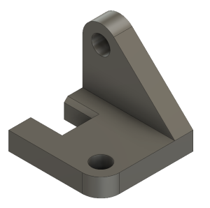
Designing a 3D model for your assignment
Use this strategy to approach the design of a 3D model:
- Draw a rough sketch of the part with pencil and paper
- Annotate your sketch with dimensions, constraints or other key features
- Plan steps to convert your drawing to a digital model (e.g. sketch, extrude, fillet, etc…)
- Apply these steps in your 3D modelling software
- Refine your model according to other details from your sketch
- Verify that all dimensions and constraints were correctly applied.
Prepare your model for 3D printing
3D modelling software can export your model in a variety of formats. Depending on how or where you 3D print your model, these formats are typically used:
- A stereolithography file (.STL)
- A Wavefront 3D model file (.OBJ)
Steps for exporting your model in these formats are generally found in the help pages of the software you are using.
3D modelling software
Use of 3D modelling software largely depends on the model you are trying to create. If you are creating:
- a geometric engineering component, CAD software is usually the best option
- an organic model for 3D animation, then 3D modelling software is best.
Get more information on 3D modelling tools .
3D Photogrammetry software
Photogrammetry software is a very useful tool for constructing 3D Models from photographs. This can be done with photos from a phone or digital camera, and then the software’s algorithms do all the work. Visit 3D Photogrammetry tools for more information.
Ways to get 3D models
3D modelling can be used in a variety of ways. You can upload a 3D model for online interaction, 3D printing, animation or for use within VR/AR applications.
You can get a 3D model via:
- CAD or 3D Modelling software — 3D Models can be created from scratch using this software
- Photogrammetry — construct 3D models from photographs at the click of a button using specialised software
- MRI/CT Scan Conversion — extract a 3D model from any CT Scan or MRI data
- 3D Scanning — scanning an object with a 3D scanner
- Online Collections — download an online 3D model
Examples of 3D models you can create using photogrammetry. Press the play buttons to interact with each model:
Trilobite 3D model
Trilobite by Nick Wiggins on Sketchfab
Kangaroo Cranium 3D Model
Kangaroo Cranium by Nick Wiggins on Sketchfab
Model of sculpture ‘A student’s head’ 3D Model
Model of sculpture ‘A student’s head’ by The University of Queensland Library on Sketchfab
Find existing 3D models
Find designs to download and use under a Creative Commons Licence from:
- Thingiverse — a MakerBot website for sharing 3D models
- Yeggi — 3D model search engine
- NIH 3D Print Exchange — a collection biomedical 3D models that include, anatomy objects, proteins, cells and tissues
Museum collections
Some museums are now making parts of their collections available as scans for home 3D printing:
- British Museum Exhibits on Sketchfab
- The New York Metropolitan Museum of Art on Thingiverse
- Smithsonian
Types of Assignments Copyright © 2023 by The University of Queensland is licensed under a Creative Commons Attribution-NonCommercial 4.0 International License , except where otherwise noted.
Share This Book

8,902 assignments 3d models found
wildcat partnership test assignment for low-poly pbr modelling

hyundai creta
ring tiffany 075 ct
Modern Cultural Center

drug heroine molecule

Residence House
modern residential building 8
round leather armchair
aim-120 missile
Facility Interior
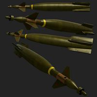
gbu-10 pavewayii missile
Forest Bow, Arrow and Quiver Set

Crhistmas wreath
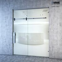
MWE Nano Sliding door system
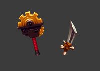
Fantasy Weapons
high-rise building
Office chair 01

of Christmas decoration tree
medieval templar sword
Eye Glasses Version 1 (High-Poly)

Eye Glasses Version 2 (Low-Poly)

B&O BeoPlay A8 3D model

residential house with swimming pool

Slide Puzzle

ktRainbowPolygons maya mel script
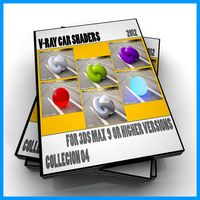
VRay Car Shaders Max 9 3D Model
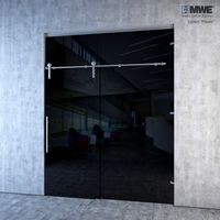
MWE "Klassic" Sliding door system
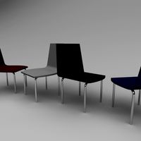
Simple Chair

Refractor Telescope with Vray Materials
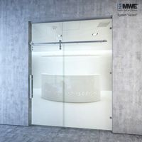
Sliding door system "Akzent" by MWE factory

stool 3 colors red white and black
Metal Trims
mexican monument - angel of independence
mexican monument - monument to the revolution

Animated Present Box

Eye Glasses Version 3 (High-Poly)
wizards house
macintosh 128k

Sci-Fi Combat Mech - FK rigged

mexican landmark - latinamerican tower

Animated Desert Eagle

dandelion street decoration

General Hospital
slab table - river
Pierre Cardin 3D Baby Cot & Changing Cabinet
ef2000 typhoon british 4
operator and

grenade f-1 low-poly
bedroom scene
cutting board
MM Lampadari Papillon 7207-8 Pendant Light

ch-53e super stallion

Chess Board
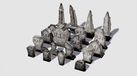
helloween tombstone pack

modern house
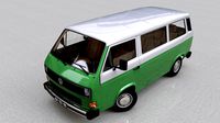
volkswagen t3 transporter caravelle - 1982
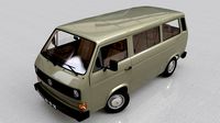
volkswagen transporter t3 - 1979

fence with a spiral protective barrier no 3

f1 white bull wb16 2020

c-130 hercules
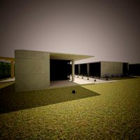
house 140m2
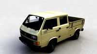
volkswagen transporter pickup double cab syncro 1987
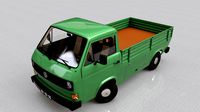
volkswagen transporter t3 pickup - 1979
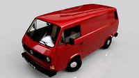
volkswagen transporter t3 cargo - 1979
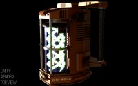
sci-fi container

table accessory

citroen hy pickup 1948
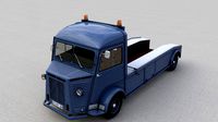
citroen hy truck 1950
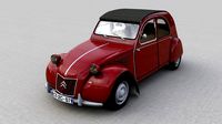
citroen 2cv az 1957
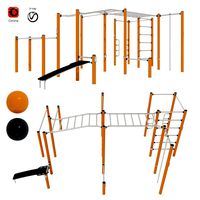
Street Workout - COMBI 5
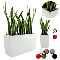
sansevieria in the pot lechusa cararo
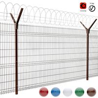
fence with a spiral protective barrier no 2

f1 ferrari sf1000 season 2020
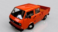
volkswagen transporter t3 pickup doble cab - 1979
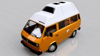
volkswagen t3 camping westfalia joker - 1980

female head 2
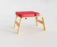
yoga chair sports equipment gymnastic mat
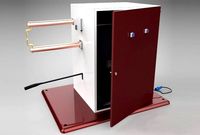
Spot Welder Machine
realistic pita bread

simple tube - toothpaste

f22a raptor

classic villa revit and lumion with 3d grass
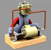
experimental steam engine with horizontal moving cylinder

sci-fi panels kitbash set
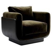
Ebisu Armchair

Military Combat Hexacopter Drone

set of large desert rock formations
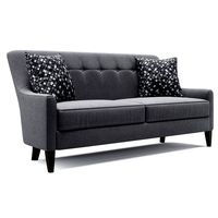
talbot sofa
citroen hy truck 1950 and citroen 2cv 1957
Delta Modular Benches
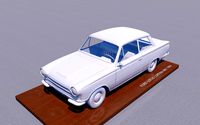
f lotus cortina mk1 1963
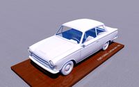
f consul cortina mk1 - 1962
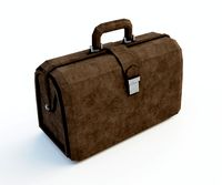
Brown leather bag
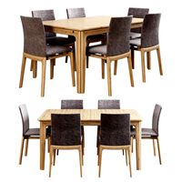
skovby set 26-table 63-chair

talbot armchair
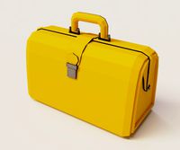
Yellow valise

Chrysler 300 SRT 8
Street Workout - COMBI 3

3D Assignment Models
- New & Unrated
- $200 to $300 (0)
- $100 to $200 (1)
- $1 to $100 (8)
- Enter custom price range
- On Sale
- .3ds (3D Studio)
- .blend (Blender)
- .c4d (Cinema 4D)
- .fbx (Autodesk FBX)
- .gltf (GL Transmission Format)
- .ma/mb (Maya)
- .max (3DS Max)
- .stl (StereoLithography)
- .unitypackage (Unity Game Engine)
- .upk/uasset (Unreal Game Engine)
- .usdz (USDz Apple)
- Low Poly (7)
- Learn more. " href="https://www.turbosquid.com/Search/3D-Models/enhanced-licenses/assignment">Enhanced Licenses
- Exclude Editorial (7)
- Exclude Branded (7)
- Learn about Editorial uses
- Learn about Branded Assets
- Learn more. " href="https://www.turbosquid.com/Search/3D-Models/real-time/assignment" class="filter">Real-Time
- Learn more. " href="https://www.turbosquid.com/Search/3D-Models/assignment?certification_id=7">StemCell
- Higher Prices
- Lower Prices

SELECT ENHANCED LICENSE
- $10,000 in Legal Protection (Indemnification)
- Uncapped Legal Protection (Indemnification)
- Waiver from injunctive relief
- Assignable model rights
- $1,000,000 in Legal Protection (Indemnification)
- $250,000 in Legal Protection (Indemnification)
- World’s best 3D model collection
- Sell Your 3D Models
- 3D Modeling Resources
Contact Support
- Open Support Ticket
- Chat with Support 24/7
- Search Knowledge Base
- Terms of Service
- 3D Model License
- Privacy Policy
- Brand Management
- Enterprise Accounts
- Company Info
- Select Language
Your Cart ... View Full Cart Generate Quote Print Cart Email Cart Open Support Ticket Chat with Support 24/7
There are currently no models in your cart.
Payment Method Add a Payment Method
Add a Payment Change Method
Buy More, Save More
Get this item for $ when you bundle it with the items in your cart.

Assignment 3d models

3D Modeling Basics

Introduction: 3D Modeling Basics
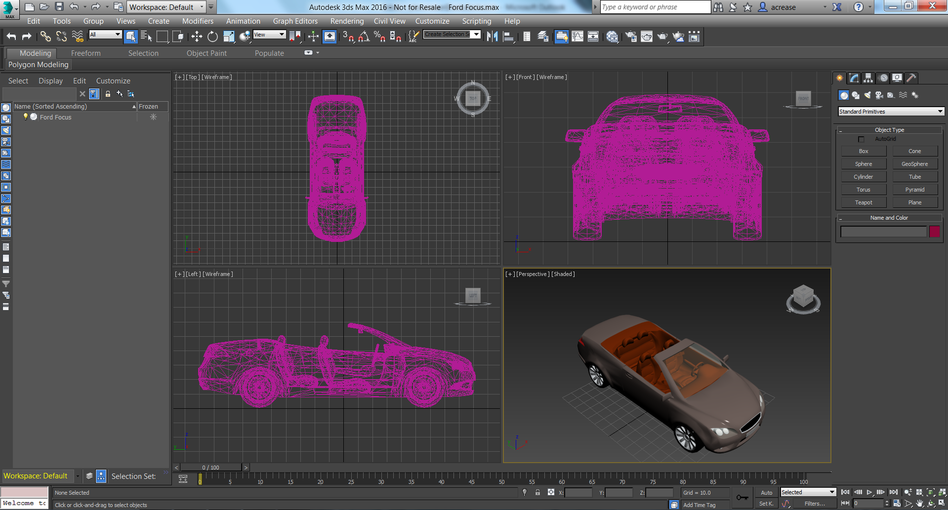
3D Modeling is used in a variety of applications to make representations of physical objects on the computer. 3D modeling is a subset of Computer Aided Design (CAD), in which you use a computer to assist in the design process for any type of design work. It is used in a variety of applications, mostly when it comes to designing parts on the computer to assist in the making or visualization of those parts. The computer model is used to communicate dimensions, material types, etc. to anyone viewing the design, and can be used to make control paths for Computer Numerical Controlled (CNC) machines.
3D Modeling in general makes the product design process more efficient. Modeling programs allow you to create and visualize final products, modify and optimize the designs, and document designs, measurements, and materials easily. If you've heard of 3D printing , 3D modeling is what is used to design objects before they are 3D printed. In this Instructable you'll learn some of the basics of 3D modeling and why it is important.
Step 1: 3D Modeling in Engineering

From movies to manufacturing, 3D modeling is incredibly useful. There are hundreds of different 3D design programs out there, each for a specific application. 3D modeling allows engineers to flush out their ideas before they become reality, so most objects that you see around you were first designed in 3D design software by engineers before they were made. 3D design is extremely important for this reason: engineers, architects, and the like use 3D CAD programs to design things before building them all the time. For example, each component of your computer was modeled in 3D modeling software, each part's shape and cost was optimized for its use, and all of the models were put together in an assembly in the software to ensure that they all fit together properly. The files were then all sent to a manufacturer, where computer controlled machines were able to make all of the parts, and workers used the files to follow the assembly steps to physically build the computer that you have sitting in front of you.

Step 2: 3D Modeling in Movies

While 3D CAD programs are traditionally used in the fields of engineering, architecture, and making things in general, 3D modeling can also be applied to the field of cinematography. Artists and designers design 3D objects, creatures, and worlds in programs like Autodesk Maya or 3DS Max for animations and product visualizations. All animated movies require some sort of 3D design to create the creatures and worlds in the films, and some live action movies incorporate CGI (Computer-generated imagery) to add special effects, details, and backdrops to create the scene and incorporate elements of the film that wouldn't have been possible otherwise.
Step 3: Beginning Steps
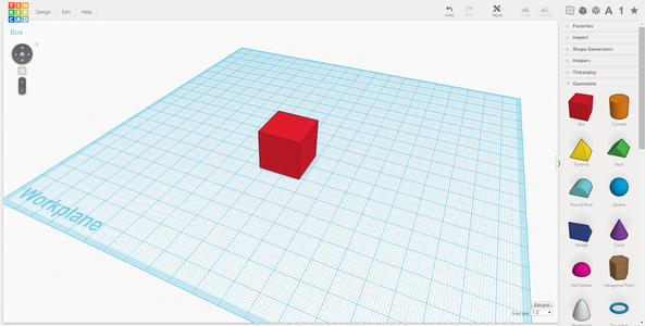
All 3D modeling programs start out with the basics of working in 3D dimensions: simple shapes and geometries. Most CAD programs start with basic shapes, either sketches of 2D shapes that can be "extruded" into three dimensions, or simple 3D shapes like blocks, cylinders, or spheres whose dimensions can be adjusted. Above is a simple box made in two different programs, Tinkercad , a simple, introductory 3D modeling program, and Autodesk Inventor , a professional 3D CAD program used for product design and simulation. You can CAD programs to modify, edit, and manipulate simple shapes to create more complicated ones, as I'll show in the coming steps.
From basic shapes and sketches, almost anything can be created using a variety of tools and templates that every CAD program provides. If you're new to a 3D modeling program, most will have introductory tutorials so that you can get familiar with the software. I'll primarily be using Autodesk Fusion 360 to show some CAD functionality, but nearly all of the procedures I'll be showing you can be found in many CAD programs. This isn't a Fusion 360 tutorial, I'm just going to show the basic functionality of 3D CAD software so that you can get started in any program you want. Some programs are a bit different than the one I'll be using, because they are set up differently, but don't be alarmed! Hopefully you'll still be able to figure them out. Your first step should be to find a 3D modeling program that suits your needs. There are a few below that I've listed. Try them out and lets start designing!
Free 3D Design Programs
- Autodesk 123D : A group of free apps and programs designed to make 3D design easy
- Tinkercad : A very simple, free online CAD program designed to create and print 3D content
- SketchUp : Another simple, easy to learn CAD program
- OpenSCAD : A 3D design tool for programmers used to make easily modifiable designs
- Blender : A 3D design tool used for more natural objects, with sculpting, rendering, and animation capabilities, used by many independent studios
Free For Students
- Autodesk Inventor : Professional mechanical design software used to create and optimize designed systems
- Autodesk Fusion 360 : Cloud-based CAD platform used to help designers through the entire designing, engineering and manufacturing processes
- Autodesk Maya : extensive 3D modeling and animation software used in many games and movies
- 3DS Max : 3D modeling and animation software used for presentations, animations, and design visualizations
Other 3D Design Software
- Solidworks : Engineering 3D design software with multiple packages for aiding in design for specific applications
- Rhino : very versatile 3D modeling software used to model everything from animals to buildings
- TurboCAD : Professional all around 3D modeling software for architecture and mechanical design
Step 4: File Types

Most 3D design software allows you to create a couple different file types. Nearly all of them allow you to create part files and assembly files, because every product is either a single element or a combination of different pieces. Parts represent single components, and assemblies represent combinations of parts or other assemblies. Drawings, a less used file type, are 2D visualizations of 3D designs that help designers convey information about their part or assembly to others on a single sheet of paper. Design programs can also contain other file types that can help designers and engineers present, simulate, animate, or manufacture their designs.
Step 5: Design Environment

All CAD programs have a similar design environment that allows you to view, edit, and document your CAD files. The file itself sits in the center of the environment, and the tools to manipulate the file are located around the edges. Again, if you are using a different program, these tools may be in different places, but I will go through the most common tools and things that you'll see in your window when you open up a file.
Step 6: Viewing Tools
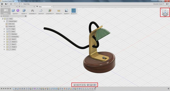
These tools (located in the bottom center of the window) are used to view your model in different orientations. With these tools, you can rotate, pan, or zoom in on your file, and even set the viewing angle normal to a specific face or plane. With these tools, you can focus your window on certain aspects of the design if you are working on them. These tools will also allow you to change the background, perspective, and lighting on your part.
Step 7: Design History

The design history bar displays all of the actions you have taken to edit your design. This tool is fairly common in design software, and incredibly useful as it allows you to go back and edit past actions you have taken in your design, including alter dimensions, remove or change features, or just scroll back and restart from a certain point. This tool is also handy in that it allows you and others to see how you created the part.
Step 8: Feature Tree

The Feature Tree, like the Design History, keeps track of your work. However, instead of displaying your work chronologically, it displays it by type of operation. In a part document, you could use the Feature Tree to see all of the sketches you have added to the part, and you can choose to view or hide operations, bodies, and features. In an assembly, you could use the Feature Tree to see what parts you have and how they are connected to each other.
Step 9: The Toolbar

The Toolbar is a very important component of CAD software, it is what allows you to actually create 3D shapes. Each section of the toolbar contains features or actions that allow you to form and edit your model. While the organization of the tools in each CAD program will be different, most of the features you will almost always be able to find somewhere along the many tabs of your CAD program's toolbar. If you can't find a specific tool, don't worry! It may go by a different name, so you could try searching for a term within your program or looking online.
Step 10: Planes, Axes, and Points

Before we start actually building things, I'd like to bring up some important pieces of 3D design software: reference geometries. These are planes, axes, and points that you can use to locate your part and its features in 3D space. All files will start out with the base reference geometries, centered around the origin, or the "zero-point", which the CAD software defines as the point (0,0,0) in 3D space. CAD programs function in a Cartesian coordinate system, so all points are defined by x,y, and z distances from the origin. The X,Y, and Z axes extend from the origin, and form the XY, YZ, and XZ planes. All of these reference geometries can be referenced in sketches and features when designing the part. Sketches, which I'll talk about soon, are defined by the plane that they lie on, and within sketches and other features, the axes and the origin can be referenced to create dimensions. You can also create new planes, axes, and points elsewhere in your 3D model, which I'll go into a bit more later.
Step 11: Parts

Part files are the basic components of 3D design software. Part files represent single components or pieces that can either be their own entity or part of a larger assembly, which I'll cover later. When designing a part, you can use a wide range of 2D sketching utilities and 3D forming tools in the modeling software to create the specific 3D shape that you want. For example, the computer front panel in the image above was created using a variety of extrusions, sculpting, and cutting features, and the car wheel rim was made with revolve, hole, and chamfer features, among other things. Both started as simple shapes and step by step the designer created the finished, detailed model. A manufacturer can use the file to obtain information about how to make the part, including the dimensions and tolerances, the material, and even the final paint coating the part should get.
Step 12: Sketches

Alright, lets start simple, in two dimensions. Within a part file, the sketch toolbar allows you to create 2D drawings that you can then use to generate 3D shapes, or just use for reference when designing a part. By clicking "Create Sketch", you can select a plane or face on which to start your sketch. A toolbar will open up with various sketch actions you can take; these include drawing tools, constraints, and dimension tools. The basic drawing tools will allow you to create some basic shapes, like rectangles, circles, arcs, polygons, and even text. Note that in Fusion 360, closed shapes get filled in, while open shapes do not.
Step 13: Dimensions and Constraints

When sketches are initially drawn, they are unconstrained. There are no dimensions or constraints associated with a line when it is first created, so you are free to move it around on the sketch plane. It is good practice in CAD programs to dimension and constrain your sketches appropriately so that they don't accidentally get messed up or altered. The quadrilateral in the first image above is only constrained in that one of its vertices is at the origin. Apart from that, I can select any of the lines or points in the sketch and drag them around. To make the shape I want, I need to use the dimension tool to make it the correct size, and the constraints to create the relationships I want between the four lines.
In the third image, you'll see I've used the dimension tool to set angles and dimensions that I want. This tool fixes those components at those specific dimensions. However, the shape can still move a fair amount, because it is not fully constrained. Instead of dimensioning every aspect of the shape, I can use the constraints toolbar to set certain rules for the shape.
In the fourth image, you can see that I have used some constraints to set some rules for my shape. I made the bottom line horizontal, I made the top line parallel to the bottom one, and I set the left and right lines equal to one another. I have now fully defined the parallelogram.
In some programs, if a sketch feature is fully defined and can no longer move, it will turn a different color to let you know that it no longer able to move. While it is important to fully define your sketches when finalizing your model both to convey to others the dimensions, and to ensure you wont accidentally change something about your part, you may want to leave a sketch unconstrained so that you can play around with its size and shape and see how it affects your 3D model.
Step 14: Other Sketch Tools

I'm not going to cover every single tool there is, but I will cover some of the most common sketch tools available so that you know what kinds of functions you can perform within a sketch.
Spline: A smooth line that will curve and adapt to intercept multiple defined points in the sketch and maintain its continuity.
Offset: Creates a similar feature to the selected entity that is offset by a given distance from the selection (if the selection is a closed loop, it will offset the entire loop outside or inside the selection)
Fillet: Rounds selected corners with a given radius
Trim: Trims a line down to the nearest endpoint (Example: if there were two intersecting lines, and the trim tool was used on one side of one line, it would remove that side and create an endpoint to the trimmed line at the intersection)
Extend: Extends a line to the next endpoint (Example: A line is drawn within a box, when the extend tool is used, the line's endpoints will extend to the edges of the box.)
Mirror: Reflects the selected sketch entity across a given line
Rectangular Pattern: Repeats selected entities a given number of times in rows and/or columns.
Circular Pattern: Repeats selected entities radially around a center point.
Project/Convert: Projects the silhouettes or edges of selected geometries or faces outside of the sketch into lines on the sketch plane.
Construction Lines: Converts selected lines into "construction lines", meaning that they can be used for alignment or guiding sketches, but are not a part of the "real" sketch (They don't interfere with closed loops or extruded features)
Step 15: Bringing Sketches Into 3D

Once you have drawn a sketch, there are few things you can do with it to take it into three dimensions. In most CAD programs, all 3D features are generated from 2D sketches. The sketches themselves define the shape or path of the feature, and different features will do different things to bring the sketch into three dimensions. When I say feature, I am referring to the action that I have performed in the workspace. Features can be any action that alters the model, and they will come up in the design history and feature tree. If you want to edit a feature that have created, all you have to do is go into the sketch that defines its shape and alter the desired portions of the sketch. The four most common types of actions are extrudes, revolves, sweeps, and lofts. All of these operations can either add or subtract material from a 3D body depending on what you want the operation to do to your part. With these tools most 3D shapes can be created, and then other tools are used to edit and refine the part.
Step 16: Extrudes
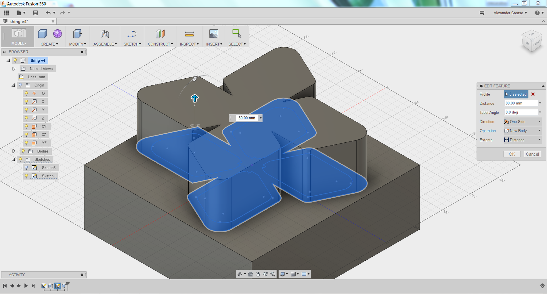
An extrude is the simplest tool needed to bring an object into 3D. What an extrude does is "pull" a 2D sketch straight up into the third dimension, as shown in the image. You can also use an extrude to cut away material from existing bodies.
To use the extrude feature, you select a closed loop in your sketch, and then set a height you want the sketch to extend to or cut to. To set the height, you can either set the height to a specified dimension or allow the shape to extrude to a selected plane, surface, or vertex in the part.
In some programs, you can extrude and add a taper at the same time, so that the feature's sides get smaller at one end. This draft or taper can assist the design process when designing for manufacturing process like injection molding, and it can also come in handy when you are creating conical or pyramid like shapes.
Step 17: Revolves

A revolve takes a closed loop in a sketch and rotates the loop around a drawn line or axis. While extrudes create planar, prismatic geometries, revolves create spherical and torus-like features.
To use the revolve feature, you select the closed loop that you want to revolve, then select the axis you want to revolve it around. Afterward, you can either set the angle at which you want your revolve to extend to, or you can revolve the part up to a certain surface, vertex, or plane.
Step 18: Sweeps
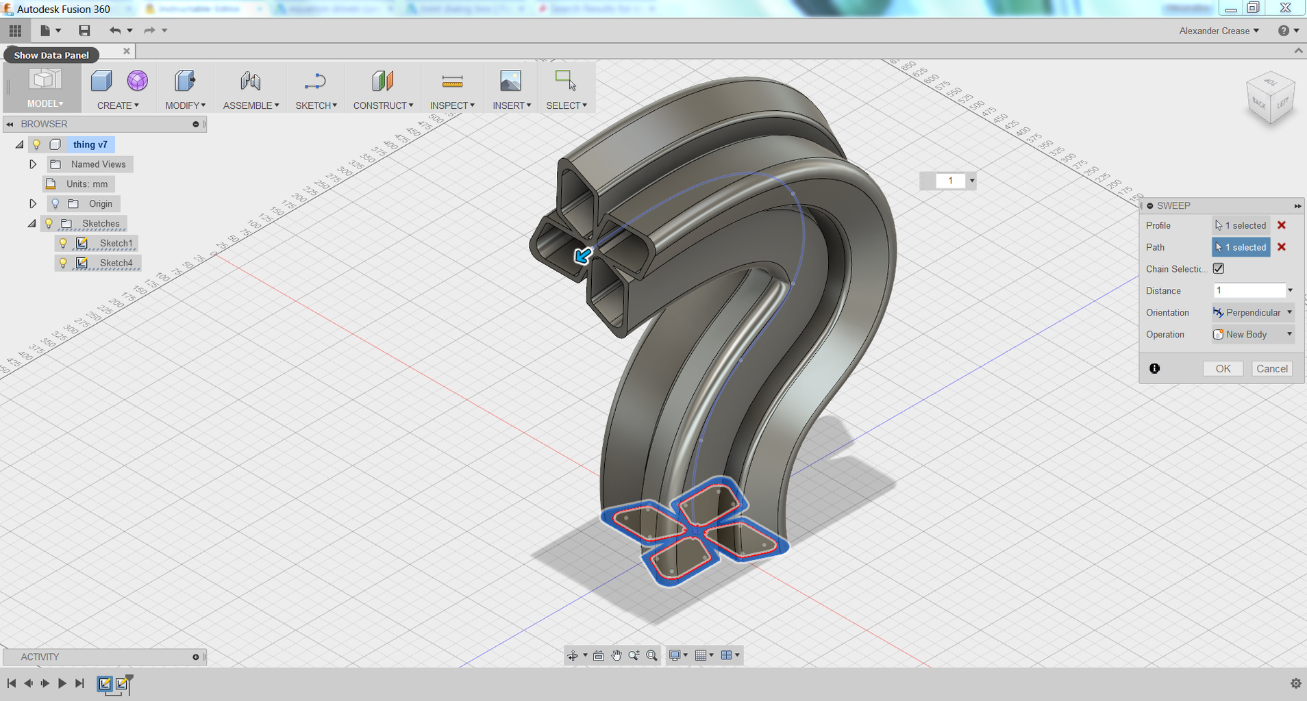
The sweep function is a lot more freeform than the extrude or revolve functions, because it allows you to take a closed loop sketch and drag or "sweep" it out along a path. Sweeps require two sketches: one defining the profile to be swept, and the other defining the path to sweep the profile along. Sweeps allow more complicated shapes to be formed, because instead of just extruding or revolving a sketch, you are dragging a sketch out along what could be a very complicated spline or curve.
To use the sweep feature, select the loop that you wish to sweep (the first sketch), and then select the path you want to sweep it along (the second sketch). If the path is too complicated and the loop profile is too large, the sweep may fail.
Step 19: Lofts

Lofts are another more complicated 3D feature. Similarly to how ships are drafted and built slice by slice, lofts allow you to select different sketches on multiple planes to create streamlined, curving geometries with non-uniform cross sections.
To use the loft tool, select (in order) the sketches that you wish to be a part of the loft. An optional step to creating a loft entails creating sketches with "guide curves", which act like sweeps in that they direct where certain points on the loft should go as the cross sections move from one shape to the next.
Step 20: Modification and Refinement Tools

After you have used some of the extrude, revolve, sweep, or loft features, you can do a couple more things to touch up your model and manipulate it to produce the desired result. Here are a few more actions you can take. Notice they are pretty similar to some of the sketch actions.
Fillet: Rounds edges and corners to a given radius. Once the part is actually manufactured, fillets prevent sharp corners. Filleting inside corners is always a good idea because rounded internal edges relieve stresses on the part and prevent shearing.
Chamfer: Chamfers create an angled face on selected edges or corners. While they are mostly added for aesthetic appeal, they can be used on parts that slide into one another to make the insertion process smoother.
Shell: Hollows out the interior of a selected body to a given wall thickness. Specified faces can be removed from the body.
Draft: Angles selected faces to a specified degree. Draft angles are useful when designing parts for molding procedures.
Holes: Allows you to place any type of hole at specified points. These include holes based on drill bit size, clearance holes, threaded holes specified by screw type, countersinks, counterbores, etc.
Mirror: reflects a selected feature or body about a selected plane.
Rectangular Pattern: Repeats selected features or bodies a given number of times in rows and/or columns.
Circular Pattern: Repeats selected features radially around an axis.
Step 21: Bodies

So what happens if you do an extrude cut or some similar operation and end up with multiple pieces in your part? While the entire thing is technically still one "part", it is split up into multiple fixed bodies. Multiple bodies can intersect yet still be of the same part, and operations can be performed on bodies to manipulate the part that you are making. For example, if you have explored some of the options within extrudes, revolves, sweeps, and lofts, you may have noticed a "new body" or "merge body" option. These selections allow you to create a new body with your feature (yet still have it possibly intersect the old one), or include the new feature as part of the original body. If you already have multiple bodies in your part, you can add, subtract, or intersect them to achieve different types of new bodies with the old ones. The four images above show the two separate bodies, and the two bodies joined, cut, and intersected in that order.
Join/Add: Adds two intersecting bodies together to form one.
Cut/Subtract: Subtracts one body from another to form one body with the negative of the other cut out of it.
Intersect: Creates one body comprising of the intersection between the original bodies.
Step 22: Reference Geometries

While sketches can be made on any flat face, sometimes you'll need to sketch on more than just the three origin planes and any faces you may have made from other features. Reference geometries allow you to create new planes, axes, and vertices other than the default reference geometries that appear when you start a new part. To fully define reference geometries, you'll need to select multiple details from your design that will "fix" the geometry in place. For example, in order to fully define a plane, you would need 3 points. To fully define a line, you need 2 points. Here are some other options when it comes to defining reference geometry:
- Offset from another plane or face
- At an angle rotated around a selected line or edge
- Tangent to a curved surface and coincident with another feature
- Between 2 selected faces or planes
- Through 2 non-conlinear lines or edges
- Tangent to a curved surface and intersecting a point
- Along a drawn path
- Through a cylindrical object
- Normal to a face in a selected area
- Through the intersection of two planes
- Through 2 points
- On a selected edge
- Perpendicular to a face and passing through a selected point
- An already existing sketch point or corner
- At the intersection of 2 edges
- At the intersection of 3 planes
- At the center of a spherical or circular feature
- At the intersection of a line and a plane
Step 23: Forming Tools

Some 3D CAD software will allow you to naturally form and sculpt your models in a much more natural way than the loft tools can. With forming features you can take a basic 3D object, like a sphere, cube, or prism, and shape it by dragging and sculpting the shapes faces, edges and vertices instead of editing and manipulating precise dimensions for shapes drawn in a sketch. This allows for the creation of much more natural objects; using forming tools making realistic looking faces, animals, and smooth, curved surfaces.
Step 24: Assemblies

Assemblies are 3D files that contain multiple parts or other assemblies. In assemblies, you can connect parts together with mates or constraints to build up a 3D model of an entire system. The assembly of the computer above is a combination of many parts and sub-assemblies needed to build the computer. Assemblies allow designers to visualize how their entire product will fit together once it is fully assembled. Within the 3D modeling program, an assembly will automatically document its bill of materials, a list of all of the components and their quantities required to build the project. If the cost of each part is known, then designers and engineers can adjust and redesign the assembly to reduce the manufacturing and assembly cost of the entire product. Engineers can use their assemblies to document the steps required to build the final product once its components have been manufactured. Working with an assembly is a little bit different than working with a part, because different tools are available to help you through the design process.
Step 25: Placing Part Files

When you open up a blank assembly document, the first thing you'll need to do is place the parts that you want into that assembly. Assemblies, like sketches, also need to be constrained, unless you want parts of your assembly to move. To add a part, you can use the "Add Part" or "Insert Component" tools to select and place your part. The first component that you place will usually be "fixed" immediately, meaning that if you tried to select it and drag it around you wouldn't be able to. The origin of the assembly will initiate at the origin of that part. The above assembly was created in Fusion 360, and the part file for the blade holder was added in.
Note: The assembly process in Fusion 360 is a bit different than in other programs. Instead of opening a new assembly file, Fusion 360 has "top-down" design methodology where you can design your entire system in one file, along with your parts. If you want to make a new part, select "New Component" when you are using a feature (like extrude, revolve, etc) to create and work on a new part. If you want to add a part you've designed in a separate design file, select "Create Base Feature".
Step 26: Joints

When you have multiple parts in your assembly, the parts will be placed, but not fixed down. The joint tool will allow you to constrain your parts in the way that you want them to be constrained in real life. By selecting multiple faces, edges, or vertices on different components, you will be able to "connect" them using mates. To create a mate, you just select the parts of each component that you want to connect, and then select what "Mate Type" you want. Here are a couple different common mating options:
Rigid/Fix Mate: This mate type will completely fix the selected components exactly where they are.
Planar/Coincident Mate: Makes two planes or faces flush with one another.
Concentric/Cylindrical Mate: Allows the two selections (usually edges, holes, or cylinders) to rotate around a common axis.
Tangent/Pin-Slot Mate: Makes two surfaces (with at least one curved one) tangent and able to slide along one another.
Ball Joint: Fixes two points together, but allows the rest of the parts to rotate freely.
Slider: The selected component will be allowed to translate along a given axis
Offset: For any mate type, you can select an offset for the mate, which will offset the two linked features by a given distance.
In order to fully define a part in the position you want it in, you may need to apply multiple mates to it. Some mates will allow you to set limits to restrict the motion of the part. For example, if you were designing a light switch, you may want to set limits to the sliding motion of the light switch so that it can only move so far.
Step 27: Movement

You may not want to fully constrain every single part in your assembly, in fact, you may have built your assembly specifically to visualize the motion of your design. There are some mates that can help you create the motion you want; for example, most mate types allow you to put limits on the mate so that you can restrict the motion of the part to a certain area. For example, the box cutter above uses a slider joint with limits to allow the blade holder piece to slide along the slot in the handle. Some software can also analyze where there are contact points between bodies, so that parts can only move until they contact other parts. Some programs will incorporate
Step 28: Animations
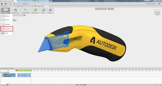
Some design software will allow you to actually animate moving components of your design. This can be useful because it allows you to record video footage of your design. Animations can be used to easily show others how a mechanism you have design works. While programs like Fusion 360 allow you to make simple animations to show the motion of a mechanism, more animation focused programs like Autodesk Maya allows designers to bring their designs to life with entire scenes and worlds in which they can "film" animated movies.
Step 29: Appearance and Rendering

If you're showing off your 3D model to someone in a presentation or paper, or you just want to get a really nice snapshot of your model, you may want to render it. Within your file you can opt to change the appearance and material properties of your model to simulate a specific material. This can be done under the "Appearance" and "Material" menus in most programs. The render itself will generate a high quality, good looking image of your model, complete with adjustable lighting, backdrops, and views.
Step 30: Drawings
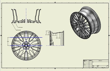
Some CAD programs will allow you to create 2D drawings of your parts on the computer. Part and assembly drawings are used by engineers to communicate information about a part to the manufacturer. Drawings contain the important dimensions, tolerances, and specific instructions required to physically make a part. They present the important information about the part on one sheet of paper, so that the manufacturer can reference it when actually machining the part. Drawings of assemblies or larger mechanisms often provide information about how to assemble the product and what motion it exhibits. In general, drawings are 2D visualizations of 3D designs that help convey information to others.
Step 31: Computer Aided Manufacturing

After a component is designed, it needs to be manufactured and made physical. Some CAD programs will assist in the manufacturing process with what is called Computer Aided Manufacturing, or CAM. CAM software helps engineers optimizing their parts for certain types of manufacturing, and is used to program Computer Numerical Controlled (CNC) machines so that they know how to machine the part. The image above shows the tool path that a CNC milling machine would take to mill out the two pockets on the face of the part. CAM software packages will sometimes be separate programs associated with specific machines, but some 3D modeling programs, Fusion 360 included, come equipped with CAM capabilities, including design guides for 3D printing, milling, or CNC routing.
Step 32: Simulations
3D design software can be used to simulate real world circumstances in order to analyze the part for its strength, behavior, and failure modes. The above animation was used to find the fundamental frequency of vibration for a designed marimba bar. 3D CAD software can be used to analyze architectural structures for their strength, determine how aerodynamic the wing of a plane is, or the dampening of the suspension of a car. Software like Solidworks and Autodesk Inventor can run extensive simulations on large assemblies in order to help designers optimize and polish their product to make it stronger, lighter and cheaper, among other things.
Step 33: Start a Project!

Now that you understand the basic concepts in 3D modeling, its time for you to try it out for yourself! If you already have an idea in mind, try to model it in the program of your choice. You could try modeling real world objects by measuring them and then making computer models of them based on those measurements, or you could try designing something you've always wanted to 3D print, like a nametag or a keychain. Tinkercad , for example, has a lot of introductory tutorials that you can 3D print once you've finished them. If not, I've made a simple 3D design starter project that you may want to get started on! It's a shadow cube, a cube-like object with the profile of a letter on each face, inspired by the cover of the book Gödel, Escher, Bach , by Douglas Hofstadter. Here's the link if you'd like to try it out!
Step 34: Resources
There's a lot more material to learn if you're interested in learning more! I didn't cover everything, but hopefully I've given you a good head start into how 3D modeling works, so that you can get going in a program yourself. There are lots more things you can do once you've learned the basics; 3D sketches, equation driven commands, parametrization, and lots more! Remember, there are always program specific tutorials and instructions if you get stuck. If you have any additional 3D modeling intro advice, comments, or questions, please comment below.
3D Model Websites
- GrabCAD : Collaborative CAD model site where users can share models they've designed and collaborate on projects
- 3Dcontentcentral : CAD sharing site with an extensive collection of 3D files supplied by companies and other users
- Thingiverse : A great site to share and find 3D printable designs
Recommendations

Fix It Contest

Books and Bookshelves Contest

All Things Pi Contest

Una's Blog
Ulster university animation student blog, assignment 1 – introduction to 3d modelling – 7th march – 50% – complete compilation post, assignment 1 – introduction to 3d modelling – 7 th march – 50%, (compilation post of all work and references during assignment 1 ), week 1 – module introduction:.
We were introduced to the new semester and given our next modules that we would be working on. We would be focusing on 3D Digital Literacy and Animated Narratives. We were given our first assignment due for the 5th of March, where we will have to Model, UV unwrap, texture and real-time render one of the following:
- Mantel Clock
- Treasure chest & treasure
- Sword & shield
- Sci-Fi door
- Magic Witch / Wizard Staff
I am most drawn to the sword and shield or the wizard staff as I think I could create an interesting design for one of these.
I had begun the research for this assignment by looking at the 3D staffs made by other 3D modellers on Sketchfab and seeing how they designed their staffs. I was looking for inspiration in order figure out what kind of staff I wanted to create as well as how to go about designing each part.
I created an Inspiration List on Sketchfab with my favourite or the most unique designs that I found: https://sketchfab.com/unamaciver/collections/staff-inspo
I was most inspired by Meltem Ozceliks Star Staff design here: https://skfb.ly/6UxDR
as well as Marlena Bayer’s Staff of Eternity design: https://skfb.ly/6XUoo
I then decided to start brainstorming and do some really rough concept sketches of potential staff designs and elements to include for my assignment model:

I continued drawing and designing more ideas for my staff for the first assignment. I began looking at staffs and weapon designs from various media and video-games.
One of my main inspirations was Final Fantasy X, an RPG game, where one of the main characters has a staff that changes design throughout the game.

I also looked at Okami, another video game, for its weapons and world designs. I love the art and style of the game and wanted to perhaps create a staff that could be found in the game.

Tsukuyomi from Okami, as modelled by daemongrave on SketchFab: https://sketchfab.com/3d-models/tsukuyomi-28197e3ae5e0480b980318db002658eb
I also looked at various staff designs and 3D artists that further helped me in my staff model concept design:

I also looked at the work of artists:
- Adrien Chan: https://www.artstation.com/artwork/1nGyxe
- M. Barutcu: https://www.artstation.com/artwork/xzwWB4
- Nathan Mulhollen: https://www.artstation.com/artwork/Aqwbzo
- Annie Boudaghain: https://www.artstation.com/artwork/8nROn
- Ayhan Ayogan: https://www.artstation.com/artwork/amoNq
These are my cleaned-up staff designs that I came up with that I liked most!:

STAFF DESIGN
For Assignment 1, I continued making progress on finalising my staff design this week and refining this further. I wanted to make a staff that could be found in a video-game like my primary references and inspiration, yet I did not want to just copy a staff and remake it instead designing my own ideas to it. I considered making a dragon staff, however I believed this would be too difficult for someone at my modelling level and I thought I wasn’t as unique as I would like for my design. I really liked the elements of the Shinto religion in Okami, and so I wanted to incorporate parts of that into staffs the final design, whilst keeping some of the fantastical designs found in weapons in Final Fantasy.

The final staff design I am working on consists of a basic staff pole with a decorative hilt and a moon and sun at the head. Tied around the centre of the pole is a Yoshiro shimenawa rope, and hanging from the staff is a lantern with mala beads and an ofuda (paper slip).

I collected the previous image references that had elements that I wanted to include in my final staff design. I tried to look at mostly objects and crafts that could be found in real life and then used those to make a magical staff for a wizard or mage.
FINAL CONCEPT DESIGN FOR STAFF:

I made a quick line art concept sketch of my final staff from the front and side to understand how it will look the entire way around in 3D. After having finished this, I was able to finally begin modelling my staff on Maya.

I am still very new to modelling and using 3D software and am finding it difficult to create my designs from basic shapes such as cubes, spheres and cylinders how I want to, however the following YouTube tutorials on Maya have been extremely helpful in the creation of my staff model.
The Game Dev Academy tutorials especially have been really useful in helping me learn how to modify and sculpt my staff model., as well as a few other videos I have also looked at.
- How to Model A Sword in Autodesk Maya & Substance Painter (Complete Workflow) | Maya Weapon Modeling: https://youtu.be/xH6L1sFpgAw
- Speed Modeling | Priestess Staff from Goblin Slayer | Maya 2019: https://youtu.be/Qh_0pES7CNU
My model currently looks a bit bare and simple, however as I continue to refine the details and shapes, I hope I can create something that I can be proud of as a 3D modelling beginner.
This week I continued working on assignment 1, completing my model.
I had a call with Michael O’Callaghan from Oaken Studios (https://www.oakenstudios.com/) who looked at my staff model and helped show me ways to create my staff model more efficiently and effectively by using simple model shapes and showing me step by step how he would go about creating the parts of my model. This was incredibly useful for parts of my model like the bottom of the staff and the bow which were more complicated steps I was less sure on how to create.
These are screenshots of Michael’s process making parts of my staff, which I then followed myself.

He also gave me tips on how I could have made other parts of my staff such as the moon in different ways which improved my understanding and techniques using Maya a lot. I found this session extremely helpful, especially by finding out ways to create parts of my staff design much faster and easier than how I was going about creating each part.
After this talk and over the weekend, I understood how to complete my model and was able to create the bow, hilt and tassel, as well as fix up other parts of my model. I cleaned up my mesh, removing any ngons that were visible and fixed imperfections in the modelling.

However, I unfortunately found that my staff had certain mistakes that I was not sure how to correct without having to delete and completely remodel parts of the staff, such as ngons that had appeared when extruding and warping the model parts. I did not have the time to do this, but thankfully most of these mistakes are not visible. In future, however, if I was animating or sending the staff professionally and had the time, I would have recreated the staff.

I was struggling to make the cloud part of my staff, however, Jodie was able to call me and show me on discord techniques they had learned in their tutorials for how I could draw vertices on a cube, and then delete the extra parts and then extrude the faces.

Thus I completed my model.
I looked at a few reference videos on YouTube to help me when completing the UV mapping and exporting of my staff.
Reference Videos:
UV Mapping Fastest and Easiest Way in Maya 2018: https://youtu.be/cy1vqLw-agk
I also had a one-on-one tutorial with Henry to help with my assignment also. This was really helpful as he looked over my model, and liked it. He suggested ways on how to export it and to put it into a UV island and import it as units.
UV Mapping my model was probably the most difficult part of the process but after completing the tasks Alec had set to us and being able to rewatch the lectures, I was able to fully UV map my entire model in order to texture it.

Final UV Mapping:

Substance Painter:
Initially I had to upload my model to Substance Painter and bake the mesh. Then I added a couple of smart materials to give the overall staff a texture. I added masked and aterial colour selector to choose specific parts of my staff to texture. I also went onto substance share where I could download specific smart materials for silk and painted wood.

After completely texturing my staff, I then painted into it to added shadows and smaller details.
I primarily followed Alec’s video lectures to texture my staff, however I did also look at other YouTube tutorials to follow, so I could learn how to add different effects. I used the following videos as reference:
- Old Beer Mug – Beginner’s guide to stylized texturing in Substance Painter: https://www.youtube.com/watch?v=kDzM_QwwNPY
Substance Painter Emissive maps: https://youtu.be/agrPbueG1Kw
- Substance Painter Beginner Tutorial : Emissive Materials: https://www.youtube.com/watch?v=kNpQ_wkEy8o
I followed the emissive tutorial which gave me the effect of my staffs lantern glowing, which I found really cool! However the emission would not load onto Sketchfab when I exported it unfortunately.

For my staff colours, I lboth used the natural colours I found on the references but also looked at the designs in Overwatch which varied between the designs and colours in skins. I was mostly inspired by Genji’s Oni and Blackwatch skins and wanted to use a similar colour scheme for my staff.

After finishing up on the texture on my staff, I was completely finished with my Staff model and then exported and uploaded it to Sketchfab.

FINAL MODEL – Moon Staff
https://sketchfab.com/3d-models/moon-staff-78b10195746a4f5f89ca799be8b0305b
For this assignment I modelled, UV unwrapped, textured and real-time rendered a Magic Witch / Wizard Staff. I designed and practiced using referencing images and creating my own concept from reference; 3D Modeling Techniques; UV unwrapping; Using basic materials & textures; Real-time rendering in my model in Sketchfab.
As a novice to 3D modelling and the programs, I think completing this assignment really helped me to understand how to model, use references, and figure out how to use programs like Maya and Substance Painter. In the beginning I spent a very long time figuring out the tools and techniques to model and had never before attempted to 3D model, so I have improved a lot from the start of the semester.
I believe the parts of the assignment I did well were modelling an intricate object for the first time. I made a 3D model just how I imagined in my concept design. I heavily used references and other 3D artists and their work in order to learn as much as possible when undergoing this assignment. I learnt how to use smart materials, layers and advanced modelling as well as UV mapping.
Some mistakes I made when creating my model were having too many triangles and vertices in the final model, and a couple of ngons I couldn’t fix without having to completely remodel the entire staff, which would not be acceptable at industry level. I also was unable to export the emission glow effect I had created in Substance Painter. I believe I could have been more precise UV Mapping the model as well as fix a couple of imperfections in the model.
If I could change or remake the model again, I think I would be more accurate in modelling to make it as low poly as possible, with fewer triangles, vertices, edges and have no ngons. I would also further my knowledge of modelling in Maya and Substance Painter by learning more about vertex manipulation and sculpting with curves, as well as watching even more tutorials on various techniques I could use to improve.
In conclusion, as someone who had only begun using 3D art programs just more than a month ago, I think I successfully created a good model that made me learn so much in the time creating it and am happy with the outcome and proud of my progress. Overall, I think my model is well made to me as my first complete 3D model.

Assignment 1 -Introduction to 3D Modelling – 7 th March – 50%
For this assignment I modelled, UV unwrapped, textured and real-time rendered a Magic Witch / Wizard Staff. In this assignment I also designed and practiced using referencing images and creating my own concept from references.
- Blog Link : https://blogs.ulster.ac.uk/unamaciver/2021/03/07/assignment-1-complete-compilation/
Portfolio Page:
- SketchFab Link : https://sketchfab.com/3d-models/moon-staff-78b10195746a4f5f89ca799be8b0305b
Maya Scene Files:
- Google Drive Link: https://drive.google.com/drive/folders/1cUax0SGuE4QHmWbko2Pmn92RrQsuqrXz
- Final Model Drive Link: https://drive.google.com/drive/folders/1odY-QFfAB6t6eidVlXS3415wLNNnfYPx
Leave a Reply Cancel reply
Your email address will not be published. Required fields are marked *
Save my name, email, and website in this browser for the next time I comment.

Want to create or adapt books like this? Learn more about how Pressbooks supports open publishing practices.
7. 3D models
When you start creating 3D models, it’s helpful to be familiar with these terms:
- Part – a single component or body that you are designing
- Dimension – a constraint applied to edge length or surface size
- Assembly – an arrangement of parts to form a construction
- CAD – Computer Aided Design
Types of 3D models
There are two types of 3D models that you might like to design:
- Geometric models — components made entirely from lines, shapes and extrusions
- Organic models — involve using curves to sculpt a mesh to a desired form.
Geometric models are typically used for engineering and construction applications, while organic models are used in 3D animations and industrial design. A combination of both types is also possible.
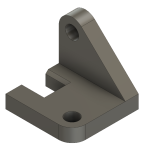
Designing a 3D model for your assignment
Use this strategy to approach the design of a 3D model:
- Draw a rough sketch of the part with pencil and paper
- Annotate your sketch with dimensions, constraints or other key features
- Plan steps to convert your drawing to a digital model (e.g. sketch, extrude, fillet, etc…)
- Apply these steps in your 3D modelling software
- Refine your model according to other details from your sketch
- Verify that all dimensions and constraints were correctly applied.
Prepare your model for 3D printing
3D modelling software can export your model in a variety of formats. Depending on how or where you 3D print your model, these formats are typically used:
- A stereolithography file (.STL)
- A Wavefront 3D model file (.OBJ)
Steps for exporting your model in these formats are generally found in the help pages of the software you are using.
3D modelling software
Use of 3D modelling software largely depends on the model you are trying to create. If you are creating:
- a geometric engineering component, CAD software is usually the best option
- an organic model for 3D animation, then 3D modelling software is best.
Get more information on 3D modelling tools .
3D Photogrammetry software
Photogrammetry software is a very useful tool for constructing 3D Models from photographs. This can be done with photos from a phone or digital camera, and then the software’s algorithms do all the work. Visit 3D Photogrammetry tools for more information.
Ways to get 3D models
3D modelling can be used in a variety of ways. You can upload a 3D model for online interaction, 3D printing, animation or for use within VR/AR applications.
You can get a 3D model via:
- CAD or 3D Modelling software — 3D models can be created from scratch using this software
- Photogrammetry — construct 3D models from photographs at the click of a button using specialised software
- MRI/CT Scan Conversion — extract a 3D model from any CT Scan or MRI data
- 3D Scanning — scanning an object with a 3D scanner
- Online Collections — download an online 3D model
Example of a 3D model you can create using photogrammetry. Press the play button to interact with the model:
Kangaroo Cranium 3D Model
Kangaroo Cranium by Nick Wiggins on Sketchfab
Find existing 3D models
Find designs to download and use under a Creative Commons Licence from:
- Thingiverse — a MakerBot website for sharing 3D models
- Yeggi — 3D model search engine
- NIH 3D Print Exchange — a collection biomedical 3D models that include, anatomy objects, proteins, cells and tissues
Museum collections
Some museums are now making parts of their collections available as scans for home 3D printing:
- British Museum Exhibits on Sketchfab
- The New York Metropolitan Museum of Art on Thingiverse
- Smithsonian
Digital Skills: Assignment Essentials Copyright © 2024 by Charles Sturt University is licensed under a Creative Commons Attribution-NonCommercial 4.0 International License , except where otherwise noted.
Share This Book
- Building Permit Drawings Assignment Help
- Landscaping Layouts Assignment Help
- Building Inspection Plans Assignment Help
- 2D Drafting Assignment Help
- Electrical Drawings Assignment Help
- Dimensioning and Annotation Assignment Help
- Solid Objects Assignment Help
- Advanced Solid Models Assignment Help
- Furniture and Product Designs Assignment Help
- Civil Engineering Drawings Assignment Help
- Architectural Drawings Assignment Help
- HVAC Drawings Assignment Help
- Interior Design Assignment Help
- Jewelry Designs Assignment Help
- Landscape Drawings Assignment Help
- Mechanical Drawings Assignment Help
- Structural Drawings Assignment Help
- Bridge Designs Assignment Help
- 3D Printed Models Assignment Help
- Finite Element Analysis (FEA) Assignment Help
A Comprehensive Guide to Successfully Completing 3D Modeling Assignments

Do you find it difficult to complete your 3D modeling assignments? You're not alone, so don't worry. 3D modeling assignments can be difficult and overwhelming for many students, but with the right strategy and some helpful advice, you can approach them with confidence. We will walk you through every step of successfully completing 3D modeling assignments in this comprehensive guide. You can build a solid foundation for your assignments by grasping the fundamentals of 3D modeling, mastering them, and studying examples from real-world applications. Additionally, we'll show you how to assess the demands of the assignment, plan your workflow, collect references, begin modeling, use textures and materials, set up lighting, and render your model. We will also offer success advice, such as the value of consistent practice and participating in online forums and communities. You'll learn the knowledge and abilities required to excel in your 3D modeling assignment help and overcome any difficulties with the help of this thorough guide. So let's get started and start your path to mastering 3D modeling!

Understanding the Basics of 3D Modeling
It's imperative to have a firm grasp of the fundamentals before delving into the world of 3D modeling assignments. It's important to become familiar with the software you'll be working with. Spend some time investigating the features, tools, and functionalities of the 3D modeling software you choose, whether it's AutoCAD, Blender, or another one. To increase your confidence, watch tutorials, read the manual, and use the software. It's also crucial to understand the fundamentals of 3D modeling. Understanding terms like polygons, vertices, edges, textures, and lighting is part of this. Spend some time learning these foundational concepts because they will form the basis of your assignments. Studying examples from real-world situations is also very helpful. Investigate the architecture, video games, movies, and product designs for ideas. Investigate the methods used by experts to produce lifelike models and attempt to use them in your assignments. You can learn a lot about the craft of 3D modeling by looking at existing models. You'll be well-prepared to take on 3D modeling assignments with confidence and creativity if you have a solid foundation in the fundamentals. These are the three main ideas you need to understand:
Familiarize Yourself with the Software
To begin a 3D modeling assignment, you must first familiarize yourself with the software you'll be working with. Spend some time investigating the features, tools, and functionalities of the 3D modeling software you choose, whether it's AutoCAD assignment help , Blender, or another one. Learn how to use the interface, the navigational controls, and the fundamental functions. You'll be able to use the program more effectively and expeditiously while modeling as a result. Watch the software's specific tutorials to learn more about its sophisticated features and methods. Reading the documentation and consulting online sources can also yield insightful information and troubleshooting hints. Most importantly, regularly practice using the software. To learn more about the capabilities of various tools and functionalities, experiment with them. Learning the program inside and out will help you work more confidently and productively, which will ultimately improve the caliber of your 3D modeling assignments.
Master the Fundamentals of 3D Modeling
You need to have a solid foundation in 3D modeling fundamentals in order to succeed in 3D modeling assignments. Understanding terms like polygons, vertices, edges, textures, and lighting is part of this. Your models' foundation is made up of these components, which also raises the caliber of the final product. Spend some time learning and honing these foundational skills because they will form the basis of your assignments. Become familiar with the creation and manipulation of polygons to give your models shape, the definition of the structure by vertices and edges, and the addition of depth and realism by textures and materials. Learn about lighting principles and how they can improve the ambiance and appearance of your 3D models. By mastering these fundamentals, you'll gain a firm grasp on the guiding principles of 3D modeling and be better prepared to produce accurate and appealing models for your assignments.
Study Real-World Examples
Studying actual examples from the real world is one of the best ways to improve your 3D modeling abilities. Investigate the architecture, video games, movies, and product designs for ideas. Investigate the methods used by experts to produce lifelike models and attempt to use them in your assignments. You can learn a lot about the craft of 3D modeling by looking at existing models. Pay attention to the level of detail, the use of textures, and the lighting strategies used. Pay attention to the composition and aesthetics as a whole. Recognize how various components work together to produce a model that is both coherent and eye-catching. You can increase your knowledge, your creativity, and your capacity to produce stunning 3D models by studying examples from the real world. Push your limits and create your own distinctive style in the world of 3D modeling by using these insights.
Step-by-Step Guide to Completing 3D Modeling Assignments
Let's get started on the step-by-step procedure for finishing your 3D modeling assignments now that you have a strong foundation. The first step is to carefully review the assignment requirements, noting the details, measurements, and any special instructions. By breaking the assignment down into smaller tasks and making a timeline, you can plan your workflow once you have a clear understanding of the requirements. Collecting images, blueprints, or sketches that are relevant to your assignment will help you create accurate and realistic models. Once you have references, you can begin modeling. Start by making the fundamental structures and shapes, and as you go along, refine your model. Applying textures and materials will improve your model's visual appeal, and lighting and rendering setup will improve its overall presentation. To improve your skills, always remember to regularly save your work. You can successfully complete your 3D modeling assignments by carefully following this step-by-step manual.
Analyze the Assignment Requirements
To successfully complete a 3D modeling assignment, one must first carefully review the instructions. Read and comprehend the specifications, measurements, and any particular instructions provided by your instructor in detail. It's critical to recognize the primary outputs required of you and to keep track of the submission deadline. Understanding the requirements in detail will help you plan your workflow more successfully. Take into account the complexity of the assignment and divide it into more manageable tasks. This will make it easier for you to allot enough time and resources to each component, enabling you to successfully complete the assignment within the allotted time. You can approach the assignment with confidence if you approach it by paying close attention to the requirements from the start.
Plan Your Workflow
Planning your workflow is essential once you are aware of the assignment requirements. You can effectively manage your time by breaking the assignment into smaller tasks and making a timeline. Assess the assignment's complexity first, and then allot more time to difficult parts that might call for further investigation or experimentation. Identify any potential bottlenecks or areas where you might need assistance or clarification by taking into account the dependencies between tasks. You can stay organized and monitor your progress by creating a visual representation of your workflow, such as a Gantt chart or a task list. Additionally, it's crucial to account for a buffer period for unforeseen difficulties or revisions. You'll be able to approach the assignment in a structured manner, stay on track, and meet the deadline with ease if you plan your workflow in advance.
Gather Reference Material
It's crucial to compile relevant reference material before beginning the modeling process. This involves gathering any relevant visual materials, such as photos, blueprints, sketches, or other visual references. Throughout the modeling process, reference material is a helpful guide that helps to ensure accuracy and realism in your work. It offers hints in terms of proportions, specifics, and overall beauty. Reference material is even more important when it comes to lighting and texturing because it enables you to comprehend how surfaces and materials should appear in various lighting situations. You can make wise decisions and build models that are more convincing and visually appealing by reading and examining the references. To make it simple to access your references during the modeling process, remember to organize them logically. You'll be prepared to create excellent and visually accurate 3D models for your assignment with a wide range of reference materials at your disposal.
Start Modeling
It's time to start the modeling process now that you have your reference materials gathered. Create the fundamental structures and shapes that will serve as the model's framework first. Bring your vision to life by utilizing the tools and methods offered by the 3D modeling program of your choice. Pay close attention to the little things and iterate, improving your model as you go. To ensure accuracy and maintain a cohesive design, take breaks and step back to evaluate your work from various angles. To prevent any potential loss of progress or data, save your work frequently. Keep in mind that modeling is an iterative process, and changes and improvements are frequently made as you go. To get the desired result, don't be afraid to experiment and try different strategies. Keep calm, pay close attention to the little things, and consult your reference materials as necessary. You can produce engaging and visually appealing 3D models for your assignment by embracing the modeling process and maintaining a systematic approach.
Apply Textures and Materials
Applying textures and materials to your model will make it more visually appealing and realistic after the basic structure has been finished. Apply textures, colors, and materials to various parts of your model using the texturing tools provided by your preferred 3D modeling program. As you choose the textures and materials, keep in mind the precise specifications of your assignment and the desired aesthetic. To make your model appear more realistic, pay close attention to small details like surface roughness, reflections, and shadows. To achieve the desired look and feel, experiment with various textures and materials, and don't be afraid to make any necessary adjustments. To ensure that the textures and materials react correctly, preview your model in various lighting situations. You can improve the visual appeal and realism of your 3D model and produce a more engaging and immersive result by applying textures and materials thoughtfully.
Set Up Lighting and Rendering
Your 3D model's overall presentation depends heavily on lighting. You can achieve the desired ambiance and mood that improves the visual impact of your model by experimenting with various lighting configurations. To draw attention to the finer points of your design and highlight its key elements, change the lighting's color, brightness, and direction. The right lighting can significantly improve your model's overall aesthetic appeal, whether it's natural lighting for a realistic look or imaginative lighting for a more artistic effect. After you are happy with the lighting arrangement, render your model to capture the complex interaction of light and shadow. The final output, which showcases your 3D model's full potential and brings it to life in a visually stunning way, is produced by rendering your model.
Tips for Success in 3D Modeling Assignments
It's critical to regularly practice and invest time in developing your skills if you want to succeed in your 3D modeling assignments. You'll gain a better understanding of modeling techniques and a greater sense of proficiency by consistently honing your craft. Additionally, participating in online forums and communities devoted to 3D modeling can offer beneficial chances for networking and learning. Engaging with people who share your interests enables you to share ideas, get feedback, and keep up with market trends. When approaching assignments, don't be hesitant to experiment and let your creativity run wild. By thinking outside the box and experimenting with various tools and techniques, you can create distinctive models that beautifully display your personal style. Keep an open mind to constructive criticism because it can help you develop and hone your skills even more. You can succeed in your 3D modeling assignments and realize your full potential as a talented modeler with practice, collaboration, and a willingness to innovate. Here are a few more pointers to remember:
Practice Regularly
The key to mastering 3D modeling is consistent practice. Set aside a specific period of time every day or week to work on your skills. You can improve your modeling skills, gain a better understanding of the software tools, and gain more comfort using intricate shapes and structures by practicing regularly. To broaden your skill set, put yourself to the test by taking on a variety of projects and exploring various aesthetics. Consider joining online forums or communities where you can ask questions of other modelers and gain insight from their experiences. Just keep in mind that practice is a continuous process, and the more time you put into it, the better you will get at 3D modeling.
Join Online Communities and Forums
Getting involved in online 3D modeling communities and forums is a great way to advance your knowledge. These online communities give users the chance to meet others who share their enthusiasm for 3D modeling, such as students, professionals, and enthusiasts. Participating in these communities enables you to get advice, feedback, and support from more seasoned participants. It is a great place to pick up new skills, find fresh ideas, and keep up with the most recent developments in the industry. You can promote a sense of community and continuously broaden your knowledge base by actively taking part in discussions, sharing your work, and giving feedback to others. These communities also frequently provide tools like webinars, tutorials, and industry news that can help you develop as a 3D modeler. Utilize the advantages of online communities to network, educate yourself, and work together with like-minded individuals as you progress in learning 3D modeling.
3D modeling assignments can at first seem overwhelming, but with a strong foundation and a methodical approach, you can successfully approach them. Start by learning the fundamentals of 3D modeling, which includes becoming familiar with the software and becoming an expert in concepts like textures and polygons. Insights and inspiration can be gained from looking at examples from real-world situations. Once you have the necessary information, complete your assignments successfully by following a step-by-step procedure. Analysis of the requirements, workflow planning, gathering of reference materials, and modeling with careful attention to detail and iterative revision. Your models will become more realistic when textures, materials, and lighting are applied. Don't forget to regularly practice to improve your abilities and to join online communities to interact with other enthusiasts and professionals. Think outside the box and embrace creativity because doing so will distinguish your work. You can confidently complete 3D modeling assignments and keep developing as a skilled modeler with commitment, perseverance, and the appropriate approach.
Post a comment...

Sign In or Create Account
Forgot password.
If you don't receive the email within an hour (and you've checked your Spam folder), email us as [email protected].
Assignment Model | Linear Programming Problem (LPP) | Introduction
What is assignment model.
→ Assignment model is a special application of Linear Programming Problem (LPP) , in which the main objective is to assign the work or task to a group of individuals such that;
i) There is only one assignment.
ii) All the assignments should be done in such a way that the overall cost is minimized (or profit is maximized, incase of maximization).
→ In assignment problem, the cost of performing each task by each individual is known. → It is desired to find out the best assignments, such that overall cost of assigning the work is minimized.
For example:
Suppose there are 'n' tasks, which are required to be performed using 'n' resources.
The cost of performing each task by each resource is also known (shown in cells of matrix)
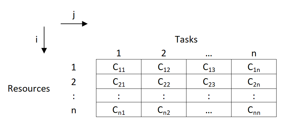
- In the above asignment problem, we have to provide assignments such that there is one to one assignments and the overall cost is minimized.
How Assignment Problem is related to LPP? OR Write mathematical formulation of Assignment Model.
→ Assignment Model is a special application of Linear Programming (LP).
→ The mathematical formulation for Assignment Model is given below:
→ Let, C i j \text {C}_{ij} C ij denotes the cost of resources 'i' to the task 'j' ; such that

→ Now assignment problems are of the Minimization type. So, our objective function is to minimize the overall cost.
→ Subjected to constraint;
(i) For all j t h j^{th} j t h task, only one i t h i^{th} i t h resource is possible:
(ii) For all i t h i^{th} i t h resource, there is only one j t h j^{th} j t h task possible;
(iii) x i j x_{ij} x ij is '0' or '1'.
Types of Assignment Problem:
(i) balanced assignment problem.
- It consist of a suqare matrix (n x n).
- Number of rows = Number of columns
(ii) Unbalanced Assignment Problem
- It consist of a Non-square matrix.
- Number of rows ≠ \not= = Number of columns
Methods to solve Assignment Model:
(i) integer programming method:.
In assignment problem, either allocation is done to the cell or not.
So this can be formulated using 0 or 1 integer.
While using this method, we will have n x n decision varables, and n+n equalities.
So even for 4 x 4 matrix problem, it will have 16 decision variables and 8 equalities.
So this method becomes very lengthy and difficult to solve.
(ii) Transportation Methods:
As assignment problem is a special case of transportation problem, it can also be solved using transportation methods.
In transportation methods ( NWCM , LCM & VAM), the total number of allocations will be (m+n-1) and the solution is known as non-degenerated. (For eg: for 3 x 3 matrix, there will be 3+3-1 = 5 allocations)
But, here in assignment problems, the matrix is a square matrix (m=n).
So total allocations should be (n+n-1), i.e. for 3 x 3 matrix, it should be (3+3-1) = 5
But, we know that in 3 x 3 assignment problem, maximum possible possible assignments are 3 only.
So, if are we will use transportation methods, then the solution will be degenerated as it does not satisfy the condition of (m+n-1) allocations.
So, the method becomes lengthy and time consuming.
(iii) Enumeration Method:
It is a simple trail and error type method.
Consider a 3 x 3 assignment problem. Here the assignments are done randomly and the total cost is found out.
For 3 x 3 matrix, the total possible trails are 3! So total 3! = 3 x 2 x 1 = 6 trails are possible.
The assignments which gives minimum cost is selected as optimal solution.
But, such trail and error becomes very difficult and lengthy.
If there are more number of rows and columns, ( For eg: For 6 x 6 matrix, there will be 6! trails. So 6! = 6 x 5 x 4 x 3 x 2 x 1 = 720 trails possible) then such methods can't be applied for solving assignments problems.
(iv) Hungarian Method:
It was developed by two mathematicians of Hungary. So, it is known as Hungarian Method.
It is also know as Reduced matrix method or Flood's technique.
There are two main conditions for applying Hungarian Method:
(1) Square Matrix (n x n). (2) Problem should be of minimization type.
Suggested Notes:
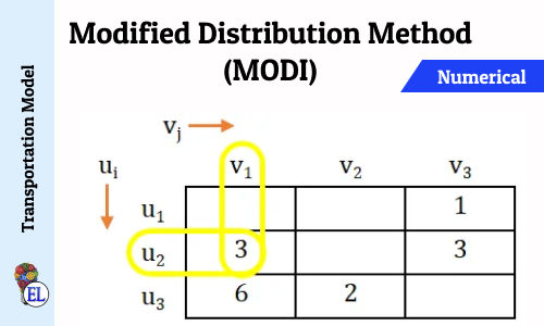
Modified Distribution Method (MODI) | Transportation Problem | Transportation Model
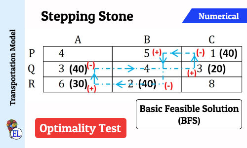
Stepping Stone | Transportation Problem | Transportation Model
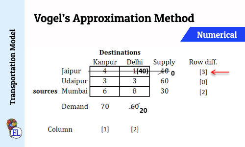
Vogel’s Approximation Method (VAM) | Method to Solve Transportation Problem | Transportation Model
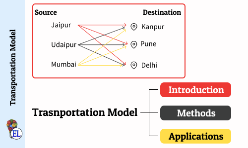
Transportation Model - Introduction
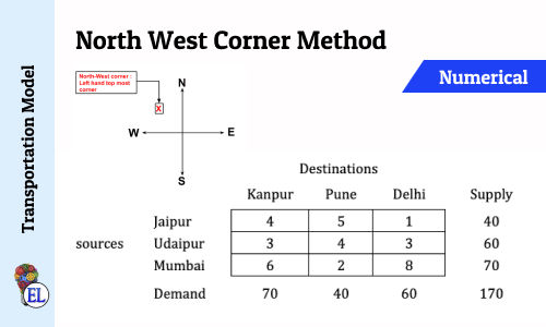
North West Corner Method | Method to Solve Transportation Problem | Transportation Model
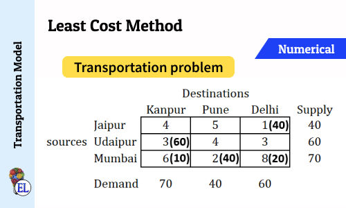
Least Cost Method | Method to Solve Transportation Problem | Transportation Model
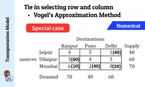
Tie in selecting row and column (Vogel's Approximation Method - VAM) | Numerical | Solving Transportation Problem | Transportation Model
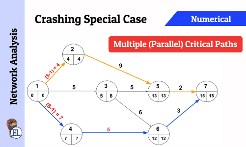
Crashing Special Case - Multiple (Parallel) Critical Paths
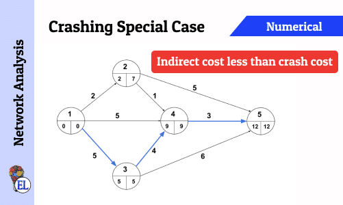
Crashing Special Case - Indirect cost less than Crash Cost
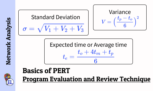
Basics of Program Evaluation and Review Technique (PERT)
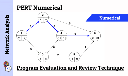
Numerical on PERT (Program Evaluation and Review Technique)

Network Analysis - Dealing with Network Construction Basics
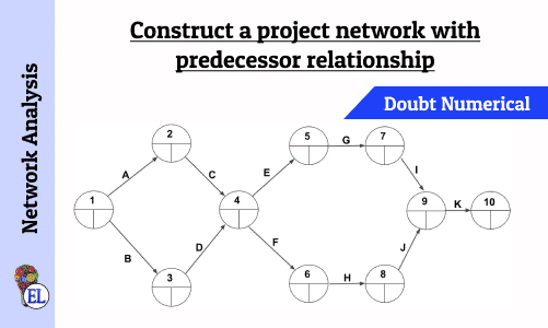
Construct a project network with predecessor relationship | Operation Research | Numerical
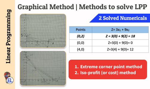
Graphical Method | Methods to solve LPP | Linear Programming
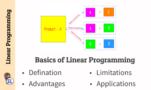
Basics of Linear Programming
Linear Programming Problem (LPP) Formulation with Numericals

All comments that you add will await moderation. We'll publish all comments that are topic related, and adhere to our Code of Conduct .
Want to tell us something privately? Contact Us
Post comment

Education Lessons
Stay in touch, [notes] operation research, [notes] dynamics of machinery, [notes] maths, [notes] science, [notes] computer aided design.

Assignment 3D print models
- 3D Print Models
- assignment 3D print models
- interior (541)
- exterior (498)
- industrial (412)
- street (362)
- decoration (346)
- military (319)
- character (313)
- architectural (309)

Gary Seven Servo Star Trek
- Staff picks
- Downloadable
- Collections
- Community members
- Sketchfab Masters
- Animals & Pets
- Architecture
- Art & Abstract
- Cars & Vehicles
- Characters & Creatures
- Cultural Heritage & History
- Electronics & Gadgets
- Fashion & Style
- Food & Drink
- Furniture & Home
- Nature & Plants
- News & Politics
- Places & Travel
- Science & Technology
- Sports & Fitness
- Weapons & Military
- Best selling
- 3D Printable
- For business Sketchfab for Teams Augmented Reality 3D Viewer 3D eCommerce 3D Configurators Find a Partner Pricing Customer Stories
Final Assignment Floor Plan 3D Model
No description provided.
CC Attribution Creative Commons Attribution
3D Modeling
In 3D computer graphics, 3D modeling (or modelling) is the process of making a mathematical representation involving any three-dimensional surface associated with an object (either inanimate or living) via special software. The product is referred to as a 3D style. It can be displayed to be a two-dimensional image by using a process called 3d images rendering or used in a computer simulation involving physical phenomena.
Keep Sensitive Data Safe With Endpoint Encryption
Common computer problems, xp internet security, how to get started in it career, audit of non-governmental organizations (ngos), history of bangladesh police, internship report on non banking financial activities and performance of idlc finance limited, gulf of carpentaria (australia), brain simulation, a common college magazine, latest post, mid-ocean ridge (mor), harnessing hydrogen at the genesis of life, ngc 5728’s faint characteristics are exposed, astronomers discover the oldest black hole ever observed, atomic hydrogen welding, variable-frequency transformer (vft).
comm 280 sec 1 – bove
Just another weblog, assignment #1- 3d printing.
A topic that I am really interested in is 3D Printing. Although 3D Printing does not totally align with the current class lectures, we will be learning more about it later into the semester. I didn’t exactly know what 3D Printing was. I had heard of it numerous times in news articles, but I didn’t really know how exactly 3D Printing worked. Below is my combined research and resources.
WHAT IS 3D PRINTING?
3D PRINTING, also known as ADDITIVE MANUFACTURING, can be defined as a process that builds layers to create a three-dimensional solid object from a digital model .
How Does It Work?
- It all starts with making a virtual design of the object you want to create.
- You can do this by using..
- a 3D modeling program (if you want to create a totally new object )
- a 3D scanner (to make a 3D digital copy an existing object )
- Once the virtual design is finalized (by either the scanner or modeling program) the digital file is then prepared for printing .
- To prepare the file, 3D modeling software then “slices” the final virtual model into hundreds or thousands of horizontal layers.
- Next the sliced file is uploaded in a 3D printer .
- When uploaded the printer is able to recreate the object layer by layer.
- The 3D printer reads every slice (or 2D image) and blends each layer with hardly any visible sign of the slicing
- The result a result the three dimensional object.
- Lastly the 3D printer prints the desired object .
- Although all are additive, there are several different types of 3D printers.
- The type used determines the process of how the object is physically printed and the materials used to make it.
Types of 3D Printers
In 2010, the American Society for Testing and Materials (ASTM) developed a set of standards that classify the Additive Manufacturing processes into 7 categories consisting of: (3dprinting.com)
- 1. Vat Photopolymerisation
- photopolymer resin is hardened with UV light source
- 2. Material Jetting
- material is applied in droplets through a small diameter nozzle, similar to how an inkjet paper printer works, but it is applied layer-by-layer to a build platform making a 3D object which is then hardened by UV light
- 3. Binder Jetting
- powder base material is spread in equal layers and liquid binder is applied through jet nozzles that “glue” the powder particles in the shape of a programmed 3D object
- 4. Material Extrusion
- nozzle extrudes melted matieral to form layers which harden immediately after extrusion [method of rapid prototyping]
- 5. Powder Bed Fusion
- high power laser fuses small particles of plastic, metal, ceramic or glass powders into a mass that has the desired three dimensional shape
- 6. Sheet Lamination
- sheets of metal, paper or a form of polymer in which material is bound together with external force
- 7. Directed Energy Deposition
- printer’s aparatus, usually a robotic arm, consists of a nozzle that deposits metal powder or wire on a surface and an energy source (laser, electron beam or plasma arc) that melts it, forming a solid object [method of rapid manufacturing]
Benefits of 3D Printing
- Customization
- 3D printing processes allow for mass customisation — the ability to personalize products according to individual needs and requirements.
- allows you to customize the design (geometry) of each object, you can also customize the materials used in production.
- able to create complex geometries that can be manufactured in no other way
- Applications are being developed to materialize complex components that are proving to be both lighter and stronger than their predecessors.
- Notable uses are emerging in the aerospace sector where these issues are of primary importance.
- unlike conventional manufacturing, where added complexity dramatically increases per unit costs – with 3D printing production it does not
- For industrial manufacturing, one of the most cost-, time- and labour-intensive stages of the product development process is the production of the tools.
- For low to medium volume applications, industrial 3D printing — or additive manufacturing — can eliminate the need for tool production and, therefore, the costs, lead times and labour associated with it.
- because of the complexity advantages stated above, products and components can be designed specifically to avoid assembly requirements with intricate geometry and complex features further eliminating the labour and costs associated with assembly processes.
- Sustainable
- an energy-efficient technology that can provide
- environmental efficiencies in terms of both the manufacturing process itself, utilising up to 90% of standard materials, and, therefore, creating less waste, but also throughout an additively manufactured product’s operating life, by way of lighter and stronger design that imposes a reduced carbon footprint compared with traditionally manufactured products.
- a local manufacturing model, whereby products are produced on demand in the place where they are needed — eliminating huge inventories and unsustainable logistics for shipping high volumes of products around the world.
WHO ARE THE MAJOR PLAYERS?
3D Printing Marketplaces
A 3D-PRINTING MARKETPLACE is a website where users buy, sell and freely share digital 3D printable files for use on 3D printers.
The marketplace arranges 3D Printing Service sources and facilitates the account management, infrastructure, server resources and guarantees safe settlement of payments.
Some of the marketplaces also offer additional services such as access to global networks of 3D printers, 3D printing on demand, location of commercial 3D print shops, and even sell associated software for model rendering.
The Impact on Other Industries
The worldwide 3D printing industry is expected to grow from $3.07B in revenue in 2013 to $12.8B by 2018, and exceed $21B in worldwide revenue by 2020. As it evolves, 3D printing technology is destined to transform almost every major industry. Today, 3D printing is being applied to materials ranging from chocolate to cells to concrete, and being used by corporations, departments and consumers. It has and will continue to provide many solutions as it reshapes product development and manufacturing. 3D Printing will only create more opportunities in almost every industry.
The Major Areas That Have Been Affected
By Use of 3D Printing Include:
Suller Inc.
Smithsonian, american pearl.
- Lowe’s
Adobe Photoshop CC
- Dewar’s
- Mondelez Int. Oreo Cookie
Natural Machines
WHAT BRANDS ARE UTILIZING 3D PRINTING THE MOST?
Brands Using 3D Printing
**Brands’ campaign incentives/ marketing tools used in association with their 3D printed products
January 9, 2015 http://www.kdmpop.com/2015/01/How-Brands-Are-Using-3D-Printing-at-Retail.cfm
In November of 2014, Target collaborated with 3D printer, Shapeways, providing an exciting opportunity for online shoppers to “be the designer”. Available at Target.com, shoppers can select 3D keepsakes including jewelry charms and pendants, then personalize them by choosing the color, size and materials such as plastics and metals. Engraving options add even more personalization. One of the goals for this market was to provide affordable 3D printed pieces with prices starting at just $7.99 for plastic charms. This is the first collaboration that Shapeaways has had with a major retailer.
March 26, 2014 http://www.techrepublic.com/article/3d-printing-10-companies-using-it-in-ground-breaking-ways/
Hasbro recently announced a partnership with 3D Systems, the company that first commercialized 3D printing, to develop and commercialize 3D printers later this year for children’s toys and games. Hasbro has a range of children’s franchises that may be featured for 3D printing, including My Little Pony, Playskool, and Sesame Street.”We believe 3D printing offers endless potential to bring incredible new play experiences for kids, and we’re excited to work with 3D Systems, a recognized industry leader in this space,” Hasbro President and CEO Brian Goldner said in the press release about the announcement in February.
November 27, 2013 http://www.imediaconnection.com/content/35445.asp#singleview
Coca-Cola’s recent venture into 3D printing to promote its new mini-sized bottles in Israel. The beverage giant and lifestyle brand, working with the GefenTeam agency, allowed customers to create virtual replicas of themselves using a mobile app. Those that took good care of their virtual selves by feeding and buying it clothing were invited to Coke’s headquarters in Israel. There, using a 3D scanner and a high-resolution 3D printer, the company created “mini me” figurines made of colored sandstone. Not only are the mini figurines relevant to the product being launched, but they are also directly in line with Coke’s overarching marketing strategy to create personal relationships with its customers. According to an article in the company’s digital magazine, “Coca-Cola is moving from promoting happiness to provoking it.
Stuller’s Create Bar Makes Designing Custom Jewelry Easy. The Create Bar is an in-store interactive kiosk where the jeweler can meet with tech-savvy customers and help them create highly personalized jewelry. CounterSketch Studio is a 3D rendering tool that allows jewelers to use prototypes and Stuller’s huge inventory of digital models to begin the process of creating a custom jewelry design. As customers provide feedback, the system performs
Disney introduced its “D-Tech Me” experience. Using 3D scanners and printers, the company recreated the famous carbon freezing scene from “The Empire Strikes Back” by putting the likenesses of visitors onto Han Solo’s body frozen in carbonite. During the summer of 2013, Disney created custom Stormtrooper figurines featuring fan faces. After 10 minutes with a 3D scanner, a 7.5 inch Stormtrooper replica was printed and sent to customers’ homes for a price of $99.95. The company also developed software that allows consumers to create and 3D print their own toys. Or check out Disney’s “Papillon,” a technology for 3D printing expressive, animated eyes on interactive characters.
As part of its “MAKEwithMOTO” tour, the company promoted the Moto X smartphone by traveling across the country to host 16 mini “make-a-thons.” At the events, attendees were able to create exclusive Moto X accessories using a 3D printer, such as NFC-enabled dog tags, tessellation bracelets, and phone covers.
August 29, 2013 http://adage.com/article/news/3d-printing-adds-dimension-marketing/243870/
Belgian Insurance provider DVV and Happiness Brussels introduced a service called “Key Save,” rolling out next month, which allows customers to scan their keys and save the data on a secure server. Whenever they lose their keys, they can take their data to a 3D printer and create a new one. It’s a boon not just to customers, but to the insurance company as well, since the companies lose money yearly on replacing homeowners’ locks.
In January of 2013 Nokia made available a 3D printing kit so its customers could print out customized covers for the Lumia 820. The kit is part of the Nokia 3D Printing Community Project, what Nokia Community & Developer Marketing Manager John Kneeland described on the Nokia blog as the “spiritual successor to the great granddaddy of customizable phones, the Nokia 5110 and its rainbow collection of removable faceplates.”
July 8, 2015 http://www.marketwatch.com/story/amazon-3d-printed-products-store-now-offering-customization-of-popular-video-game-characters-from-smite-primal-carnage-and-infinity-blade-2015-07-08
Amazon 3D Printed Products Store Now Offering Customization of Popular Video Game Characters from Smite, Primal Carnage and Infinity Blade. Amazon’s 3D Printed Products store enables customers to be designers and customize their favorite video game characters. The easy-to-use personalization widget allows customers to create, design and customize characters by pose, accessory, animation and base.
Customers start by selecting the game character they wish to personalize and launching the personalization widget. Next, customers can explore an almost infinite number of poses, animation designs, accessories and more depending on the game character to put their individual style on the character.
The 3D Printed Products store gives customers access to thousands of fun and unique items, many that can be customized by material, style and color variations, and personalized with text. The 3D Printed Products store is one of the largest online destinations to discover customizable 3D printed products and features convenient search tools, interactive 3D preview functionality and the product personalization widget.
Oct 1. 2014 http://www.lego.com/en-us/mindstorms/videos/3d-printer-by-will-9f5e042fab574bbd9a557622b29613fb
Lego Mindstorm fan Will has created a supercool LEGO 3D printer concept! He made it using LEGO MINDSTORMS EV3 and additional bricks, motors and sensors. How it works? It is programmed to convert digital LEGO models into physical prints, all using 2×2 LEGO bricks! Check out this interview from World Makerfaire in New York to hear him talk about his AW3SOME creation!
11/13/2013 http://www.forbes.com/sites/ericmack/2013/11/13/smithsonian-now-allows-anyone-to-3d-print-some-historic-artifacts/
The Smithsonian Institute introduced Smithsonian X 3D, a new effort and web portal to create 3D renderings of its vast and fascinating collections of more than 137 million objects. For some months now, the Smithsonian’s Digitization Program Office has been using an assortment of 3D scanners and other technology in partnership with entities like Autodesk ADSK +0.86% to create 3D models of artifacts that range from whale fossils and bees to Abraham Lincoln’s head and the Wright Brothers’ flyer — even entire archaeological sites have been scanned and rendered. Using Web GL in a regular browser, anyone can examine, manipulate and even print 3D renderings of almost two dozen priceless historic artifacts from around the world.
Nike reported 13% growth for its latest quarter. CEO Mark Parker has previously stated that 3D printing technology has been a big boost for the company recently. Nike made 3D printed cleats for the 2014 Super Bowl. The Nike Vapor Laser Talon has a 3D printed plate and cleats made from selective laser sintering technology, and the Vapor Carbon Elite also has parts produced with a 3D printer. The Nike Vapor Laser Talon, which weighs 5.6 ounces, was designed for football players running the 40 yard dash on football turf. The company indicated that it has plans to extend its use of 3D printing in future products, but hasn’t revealed details.
Can’t decide on an engagement ring? With American Pearl jewelry company, customers can create a unique piece of jewelry by choosing specific metals, gems, or diamonds, ordering them online, and then 3D printing them. There are eight metal options to choose from, such as platinum or rose gold, as well as an array of diamonds and other gems like sapphires and emeralds. Then, American Pearl’s CAD software makes a digital file of the custom jewelry, which is turned into a 3D printed thermoplastic wax mold via a Solidscape T-76 3D Printer. The metal is poured into the mold, the gems are added, and the piece ships within a few days. However, the service is quite expensive — the company is making jewelry that costs hundreds of thousands of dollars.
Design your own Makie doll with MakieLab, which 3D prints 10 inch flexible fashion dolls from thermoplastic. Customers can choose all of the features of the doll: face, eyes, jaw, smile, hair, and more. They are made in the London headquarters and shipped around the world. The company markets the product as environmentally friendly not only because of its custom printing that produces less waste, but also because the packaging is made from recyclable materials. MakieLab prints other games and toys, though the doll is still its most popular product.
April 29, 2015 http://adage.com/article/cmo-strategy/lowe-s-latest-wild-crazy-innovation-3d-printing/298289/
Lowe’s Innovation Labs have created a simple, user-friendly design kiosk breaks 3D printing down into three steps, where users can select a product, customize the design and print it in the material of their choice. Lowe’s service is meant to help customers with no knowledge of 3D printing create something from scratch or from a scanned item. It offers a small list of templates to get the ball rolling and specially-trained sales associates are on hand to help. Customers can also take their designs home, work on them and bring them back to be printed.
January 20, 2014 http://www.forbes.com/sites/tjmccue/2014/01/16/adobe-photoshop-adds-tools-for-3d-printing/
With today’s release of Photoshop CC, designs can be printed to a locally connected 3D printer or via built-in access to popular online 3D print services. Photoshop CC supports the most popular desktop 3D printers, such as the MakerBot Replicator (owned by Stratasys), and also supports the full range of high quality materials available on Shapeways — the 3D printing community and marketplace — including ceramics, metals, and full color sandstone. Additionally, Photoshop users can now directly upload their 3D models to the Sketchfab 3D publishing service, and embed them in their Behance profile (a social network for creatives). Adobe is simplifying the 3D print process, but these specific capabilities exist within the cloud version of Photoshop, not the stand-alone desktop software. According to the release and site, there is a free 30-day trial and plans start at $9.99/month for individual cloud access to one software solution, such as, Photoshop or Illustrator for example.
The company recently launched an iOS app, eBay Exact, which allows those who don’t own 3D printers to buy custom objects from 3D companies like Sculpteo, MakerBot and Hot Pop Factory. The items range from basic- like iPhone cases — to luxe, like $350 metal rings.
3D Systems has also partnered with Hershey’s to make a 3D printer for chocolate and other edible products. The 3D printing company said this partnership is a good way to show how the technology can be mainstream, though there is no word when the chocolate-making machine may be available. The ability to 3D print food is nothing new, as 3D systems has shown with its Sugar Lab, where the company prints icing and other sugary confections.
CULINARY INSTITUTE OF AMERICA
In 2015, 3DSystems will be teaming up with the Culinary Institute of America (CIA) to provide students the ability to experiment with edible food printing, creating “printed” creations and artful designs made of sugar. Avi Reichental, President/CEO of 3D Systems stated “Our collaboration with the CIA provides the culinary community with a unique opportunity to explore and experience the open-ended possibilities of fusing 3D food printing with traditional culinary arts.”
December 31, 2014 http://www.cnn.com/2014/11/06/tech/innovation/foodini-machine-print-food/
As further proof that you can now 3D-print anything, a company called Natural Machines has introduced a 3D printer for food. The “Foodini,” as it’s called, isn’t too different from a regular 3D printer, but instead of printing with plastics, it deploys edible ingredients squeezed out of stainless steel capsules: “It’s the same technology,” says Lynette Kucsma, co-founder of Natural Machines, “but with plastics there’s just one melting point, whereas with food it’s different temperatures, consistencies and textures. Also, gravity works a little bit against us, as food doesn’t hold the shape as well as plastic.” the company is working with major food manufacturers to create pre-packaged plastic capsules that can just be loaded into the machine to make food, even though they assure these will be free of preservatives, with a shelf life limited to five days. Other than being capable of creating complex designs, such as very detailed cake decorations or food arranged in unusual shapes, the Foodini can be useful for recipes that require precision and dexterity, like homemade pizza or filled pasta.Currently, the device only prints the food, which must be then cooked as usual. But a future model will also cook the preparation and produce it ready to eat.
Mondelez International’s Oreo cookie brand
Food manufacturing companies are exploring 3D printed foods. As 3D printing continues to gain popularity and prove to be a benefit for brands, we should see more of these collaborations in the coming year.
December 31, 2014 http://www.forbes.com/sites/jenniferhicks/2014/12/31/us-army-looks-to-3d-print-food-for-soldiers/
in December 2014, the pasta company Barilla announced a project and contest to 3D print its pasta. More than 530 national and international product designers submitted entries for new 3D printed pasta that would challenge the concept of the pasta – and make it 3D printable. Part of the investigation into 3D printing food for soldiers is more about the Army food technologists looking to develop 3D printing technology to create nutrient-rich foods that can be eaten on the battlefield or in a warfare environment. Oleksyk says nutritional requirements could be sent to the 3D food printer and meals printed each soldier’s individual dietary requirements.
The brand recently enlisted a swarm of 80,000 honey bees to 3D print a bottle of whisky as part of its “3B Printing Project.” skillfully executed by Dewar’s, the Sid Lee creative group, and New York ad agency The Ebeling Group. A transparent whisky bottle was created. Within the bottle, a starter blueprint of the bottle that mimicked a bee’s natural environment (allowing for the collection of nectar and pollen) was placed as a template on which the insects could produce wax. Essentially, an inside-out beehive was created. The result was a “3D printed” bottle made entirely of honeycomb. ** The campaign was launched with a 60 second trailer introducing the new whisky and the “3B” process. The entire event was broadcasted on Dewar’s Facebook page as the “Live in the Hive” webstream. Although this isn’t a clear-cut example of 3D printing, it demonstrates the powerful influence and possible offshoots of 3D printing for branding efforts.
TRANSPORTATION
Volkswagen Polo and DDB Copenhagen turned consumers into car designers. “The Polo Principle” campaign invited people to take control, via a website, of the automaker’s 3D printer — the one used to create the original Polo model — to design their own versions of their car. Forty of the most creative ideas were 3D printed and exhibited in Copenhagen the following May, after which the designers took their creations home. Even better, the big winner was turned into a real-life Polo.
Ford Motor Company
The auto company has been using 3D printing technology since the 1980s and recently printed its 500,000th part with a 3D printer, which was an engine cover for the new Ford Mustang. According to Ford’s website, traditional methods would take four months and $500,000, but with 3D printing, the same process takes four days and $3,000. Ford also teamed with 3D Systems Sugar Lab around Valentine’s Day this year to 3D print an edible 2015 Mustang model, made from chocolate and sugar. The company plans to work with 3D printers in the near future, using sand printing and direct metal printing.
June 23, 2014 http://www.ge.com/stories/advanced-manufacturing
GE is using laser-powered 3-D printers, 3-D “inking” and “painting” machines, and other advanced manufacturing tools to make parts and products. They recently used 3D metal printers to produce its fully redesigned new fuel injection system for jet engines, reducing components from 21 parts to 1 and incorporating geometries that are simply impossible to create using any other manufacturing method, resulting in astonishing increases in efficiency.
The airline company was one of the early adopters of 3D printing technology, and has made more than 20,000 3D printed parts for 10 different military and commercial planes. The 787 Dreamliner has 30 3D printed parts, including air ducts and hinges, which is a record for the industry. Using Stratasys 3D printers, the company also printed an entire cabin. The company also supports additive manufacturing programs at the University of Sheffield and University of Nottingham in the UK, where there is research for aerospace and other manufacturing sectors using 3D printing technology.
DIY Rockets
Last year, DIY Rockets, a global space company that was created to lower the cost of space exploration using crowdsourcing, launched a competition for people to develop 3D printed rocket motors using Sunglass cloud-based design platform. The only rules were that the designs had to be open source and the participants had to present a business case. The winner for the best rocket engine, announced in July, was Team Stratodyne, which won a $5,000 prize. The design will be created with the help of Shapeways,, the world’s biggest 3D printing marketplace.
https://en.wikipedia.org/wiki/3D_printing#Impact
http://www.kdmpop.com/blog/15827/3D%20printing
http://www.imediaconnection.com/content/35445.asp#singleview#9qXgzD1IcuVP8gaP.99
http://adage.com/article/news/3d-printing-adds-dimension-marketing/243870/
http://www.marketwatch.com/story/amazon-3d-printed-products-store-now-offering-customization-of-popular-video-game-characters-from-smite-primal-carnage-and-infinity-blade-2015-07-08
http://adage.com/article/cmo-strategy/lowe-s-latest-wild-crazy-innovation-3d-printing/298289/
http://3dprintingindustry.com/2015/07/06/makerbot-now-sold-in-all-sams-club-stores-across-usa/
https://ww http://3dprinting.com/what-is-3d-printing/#whatitisw.youtube.com/watch?v=dcX41EQ1JTo
One thought on “ Assignment #1- 3D Printing ”
Great post! Thank you for providing such a comprehensive list of information regarding 3D printing.
Leave a Reply
You must be logged in to post a comment.
First released in version : 3.2
- Model assignment
When you have a data model with objects types defined, and a selection of representations you wish to use for those object types, you can begin assigning reps to types and objects so that they can be visualized in the different visualization components of SmartSpace . As described in Object representations , Reps are assigned to objects using a key-value mapping called a Representation Mode , or rep mode for short.
- Representation Modes
Rep modes provide a simple way of assigning a rep to an object type with a persistent key name that can be referenced by other parts of your SmartSpace application.
While rep modes can be completely custom for each application (they are freely definable) SmartSpace does include some built-in rep modes that should be used at appropriate times.
- The <default> Rep Mode
Rep modes in SmartSpace are designed to provide a lot of control over how objects are visualized in the 2D web map , because they offer a way of communicating useful status information to end-users. In this sense, the benefits of rep modes are most evident when controlling the way objects are rendered to the 2D web map .
Conversely, the 3D visualization of SmartSpace is intended to provide an interface for interacting with objects in the world model, and as such rep modes are not supported to the same degree as with the web map . Within the 3D visualization, SmartSpace includes an in-built rep mode called <default> which is used to attach a single rep to an object type, typically a 3D rep from an imported Collada file. However, it is also possible to attach a 2D rep to objects using the <default> rep mode, and as such these objects will appear as 2D when viewed in the 3D site visualization.
- The ‘foreground’ and ‘background’ Rep Modes
As discussed in detail in Searches and Web maps , the SmartSpace Web maps use predefined searches to query the SmartSpace object model for a collection of objects that satisfy the parameters of a search. This group of objects must then be rendered to the SmartSpace Web Map using an appropriate representation mode. SmartSpace includes a built-in representation mode called foreground for objects that are part of what is called the foreground search . Similarly SmartSpace includes another built-in rep mode called background for when a search is being run as a background (or secondary) search alongside the primary foreground search. While Foreground and Background searches are covered in more detail in Searches and Web maps , at this point it is just important to note that these rep modes exist and should be used as the default rep mode keys for objects to be displayed in the web map .
- The ‘unselectable’ Rep Mode
Occasionally, you might require objects to appear on the web map but not be selectable by clicking. In this situation, you can create a rep mode whose name begins with unselectable . For example, you might have a search that displays workbench objects on the map and in order to make other objects located on the workbench more easy to select you would make the workbench object unselectable .
- The <selected> Rep Mode
You can replace the green halo that indicates the selected object on the web map , by assigning an image of your choice to the object, giving it the <selected> rep mode, and then using this rep mode in relevant web searches. See Customizing how selected objects are highlighted on the web map for an example.
- Custom Rep Modes
If you have the Visibility component licensed you can create custom rep modes that allow you to display decoration reps alongside objects. See Decorations and Representation Modes in the web map for an example of this. To take full advantage of these custom rep modes (and add or remove them dynamically) the SmartSpace Business rules engine must be licensed as well. To actually write the logic which controls how and when these custom rep modes are assigned requires a license for the Rules engine developer .
The Model assignment workspace
Representations can be assigned generically to all objects of a specific type (1-many mapping), or directly to objects themselves (1-1 mapping). The Model assignment workspace provides two tabulated views of these mappings: one for types and one for objects.
Click on MODEL ASSIGNMENT to display the workspace.
The workspace is described in the following sections:
- List of type-assigned reps
A list of types and their allotted representations is displayed along with their representation modes.
- Check boxes are available to allow you to indicate if this type and representation paring should be used in 2D (for example in Web maps) or in 3D (in the 3D site visualization).
- Double-clicking <Add new type rep> allows you to assign a rep to a type
- Object selector
The object selector allows you to refine the list of objects and their representations shown in the lower half of the screen.
- Choose an object type from the list to narrow the display and use <Filter by name> to find specific objects within the result set (using a partial string match)
- Choose <Background objects> to display background representations to which SmartSpace has attached a hidden system level object. (This enables you to work with background reps even when the environment becomes complex and accessing them directly from the environment display becomes difficult. See Site visualization . )
- List of object-assigned reps
A list of objects and their allotted representations is displayed along with their representation modes.
- Check boxes are available to allow you to indicate if this object and representation paring should be used in 2D (for example in Web maps) or in 3D (in the 3D site visualization)
- Double-clicking <Add new object rep> allows you to assign a rep to a type
- Copying models to Ubisense Generation 2.X products
If your installation includes a Generation 2 product such as ACS ( ACS ), a button is provided to enable you to copy models to the Generation 2 program. See Copying models for use in ACS for information on copying models, and the ACS ( ACS ) manual or online Help for examples of their use.
- Adding a representation to a type
To add a representation for a type:
- Double-click <Add new type rep> .
- Choose the object type.
- Choose the representation from the list of imported reps.
- You are working with 3D reps
- You don’t intend to change your object representation programmatically (using the Business rules engine )
- Click Save.
Use the check boxes displayed beside the new details for your object and representation pair to control how and where the representation assignment you’ve just created is used. There are two options:
Show in 2D : tells SmartSpace you want this representation/rep mode pair to be visible for this class of object when they are displayed in the web map
Show in 3D : tells SmartSpace you want this representation/rep mode pair to be visible for this class of object when they are displayed in the 3D site visualization
- Adding a representation to an object
To assign a representation to a specific object:
- Double-click <Add new object rep> .
- Choose the object.
- Use the check boxes displayed beside the new details for your object and representation pair to control how and where the representation assignment you’ve just created is used. There are two options: Show in 2D : tells SmartSpace you want this representation/rep mode pair to be visible for this class of object when they are displayed in the web map Show in 3D : tells SmartSpace you want this representation/rep mode pair to be visible for this class of object when they are displayed in the 3D site visualization
- The Model assignment workspace
Ubisense Documentation Portal

IMAGES
VIDEO
COMMENTS
Designing a 3D model for your assignment. Use this strategy to approach the design of a 3D model: Draw a rough sketch of the part with pencil and paper; Annotate your sketch with dimensions, constraints or other key features; Plan steps to convert your drawing to a digital model (e.g. sketch, extrude, fillet, etc…); Apply these steps in your 3D modelling software
Assignment 3D models ready to view, buy, and download for free. Popular Assignment 3D models View all . Download 3D model. Library (Large Space) Higher Fidelity - Tagarino. 28 Views 0 Comment. 4 Like. Download 3D model. Shiba! 243 Views 0 Comment. 7 Like. Game Asset Pipeline Assignment 2: Screwdriver. 25 Views 0 Comment. 4 Like.
Assignment model - 3D model by Kalagon. Explore Buy 3D models. For business / Cancel. login Sign Up Upload. Assignment model. 3D Model. Kalagon. Follow. 4. 4 Views. 0 Like. Add to Embed Share Report. Triangles: 30.3k. Vertices: 15.7k. More model information. No description provided. Published 6 months ago. Oct 7th 2023. Uploaded with Maya No ...
Orbit navigation Move camera: 1-finger drag or Left Mouse Button Pan: 2-finger drag or Right Mouse Button or SHIFT+ Left Mouse Button Zoom on object: Double-tap or Double-click on object Zoom out: Double-tap or Double-click on background Zoom: Pinch in/out or Mousewheel or CTRL + Left Mouse Button
19,986 Assignment 3d models found. Download or buy, then render or print from the shops or marketplaces. 3D Models below are suitable not only for printing but also for any computer graphics like CG, VFX, Animation, or even CAD. You can print these 3d models on your favorite 3d printer or render them with your preferred render engine.
The GrabCAD Library offers millions of free CAD designs, CAD files, and 3D models. Join the GrabCAD Community today to gain access and download!
The goal is to get used to blender editor and basic 3D modeling. 1. Open still_life.blend file in Blender. The scene in the file is an empty still life setup made from two scaled cubes. You see the stage in the camera view, you can rotate the view with the middle mouse button, and you can drag the view by pressing the shift key while
Please note that the 3D model database is only a Search Engine. You should visit the original websites. Most of the models can be easily imported and rendered with Autodesk 3ds Max, Maya, Blender, C4D, and Sketchup. Check for online 3d model conversions tools for your file format. Shown 1 of 75 pages
3D assignment models for download, files in 3ds, max, c4d, maya, blend, obj, fbx with low poly, animated, rigged, game, and VR options. 3D Models Top Categories ... 3D Models New & Unrated Price. $300 + (0) $200 to $300 (0) $100 to $200 (1) $1 to $100 (8) Free (0) Enter custom price range ...
This week expands on our layout sketches and begins to create a solid 3D model. Through the use of some basic and advanced features, we learn various tools of the trade to create complex 3D shapes. We also expand our Autodesk® Fusion 360™ knowledge and skills into the Patch workspace and explore how to add or remove solid geometry with surfaces.
3D Assignment Models Free Download in various formats such as OBJ FBX STL DAE GLB ready to use for Unity/Blender/Maya/Cinema4D/Autodesk 3ds Max
Step 3: Beginning Steps. All 3D modeling programs start out with the basics of working in 3D dimensions: simple shapes and geometries. Most CAD programs start with basic shapes, either sketches of 2D shapes that can be "extruded" into three dimensions, or simple 3D shapes like blocks, cylinders, or spheres whose dimensions can be adjusted.
Overall, I think my model is well made to me as my first complete 3D model. ***** Assignment 1 -Introduction to 3D Modelling - 7 th March - 50%. For this assignment I modelled, UV unwrapped, textured and real-time rendered a Magic Witch / Wizard Staff. In this assignment I also designed and practiced using referencing images and creating my ...
Designing a 3D model for your assignment. Use this strategy to approach the design of a 3D model: Draw a rough sketch of the part with pencil and paper; Annotate your sketch with dimensions, constraints or other key features; Plan steps to convert your drawing to a digital model (e.g. sketch, extrude, fillet, etc…); Apply these steps in your 3D modelling software
Load in 3D viewer Uploaded by Anonymous The CAD files and renderings posted to this website are created, uploaded and managed by third-party community members. This content and associated text is in no way sponsored by or affiliated with any company, organization, or real-world good that it may purport to portray.
2613 "assignment" 3D Models. Every Day new 3D Models from all over the World. Click to find the best Results for assignment Models for your 3D Printer.
3D modeling assignments can at first seem overwhelming, but with a strong foundation and a methodical approach, you can successfully approach them. Start by learning the fundamentals of 3D modeling, which includes becoming familiar with the software and becoming an expert in concepts like textures and polygons. Insights and inspiration can be ...
3D CAD Assignment | 3D CAD Model Library | GrabCAD. Join 13,400,000 engineers with over 5,980,000 free CAD files. The CAD files and renderings posted to this website are created, uploaded and managed by third-party community members. This content and associated text is in no way sponsored by or affiliated with any company, organization, or real ...
Join 13,400,000 engineers with over 5,980,000 free CAD files. ... The GrabCAD Library offers millions of free CAD designs, CAD files, and 3D models. Join the GrabCAD Community today to gain access and download!
Assignment 3-3D Modeling and Printing. Stefanie Darby · Follow. 6 min read · Nov 13, 2019--Listen. Share. 3D Model making and drafting has been around for some time now. Some people may think ...
There are two main conditions for applying Hungarian Method: (1) Square Matrix (n x n). (2) Problem should be of minimization type. Assignment model is a special application of Linear Programming Problem (LPP), in which the main objective is to assign the work or task to a group of individuals such that; i) There is only one assignment.
2 Assignment 3D print models, available for download in STL, OBJ and other file formats, ready for printing with FDM, SLS and other 3D printers. Our website uses cookies to collect statistical visitor data and track interaction with direct marketing communication / improve our website and improve your browsing experience. ...
Orbit navigation Move camera: 1-finger drag or Left Mouse Button Pan: 2-finger drag or Right Mouse Button or SHIFT+ Left Mouse Button Zoom on object: Double-tap or Double-click on object Zoom out: Double-tap or Double-click on background Zoom: Pinch in/out or Mousewheel or CTRL + Left Mouse Button
Article. In 3D computer graphics, 3D modeling (or modelling) is the process of making a mathematical representation involving any three-dimensional surface associated with an object (either inanimate or living) via special software. The product is referred to as a 3D style. It can be displayed to be a two-dimensional image by using a process ...
a 3D modeling program (if you want to create a totally new object) a 3D scanner (to make a 3D digital copy an existing object) Once the virtual design is finalized ... One thought on " Assignment #1- 3D Printing " dcn101 September 11, 2015 at 3:55 pm. Great post! Thank you for providing such a comprehensive list of information regarding 3D ...
Model assignment. When you have a data model with objects types defined, ... Conversely, the 3D visualization of SmartSpace is intended to provide an interface for interacting with objects in the world model, and as such rep modes are not supported to the same degree as with the web map.