For IEEE Members
Ieee spectrum, follow ieee spectrum, support ieee spectrum, enjoy more free content and benefits by creating an account, saving articles to read later requires an ieee spectrum account, the institute content is only available for members, downloading full pdf issues is exclusive for ieee members, downloading this e-book is exclusive for ieee members, access to spectrum 's digital edition is exclusive for ieee members, following topics is a feature exclusive for ieee members, adding your response to an article requires an ieee spectrum account, create an account to access more content and features on ieee spectrum , including the ability to save articles to read later, download spectrum collections, and participate in conversations with readers and editors. for more exclusive content and features, consider joining ieee ., join the world’s largest professional organization devoted to engineering and applied sciences and get access to all of spectrum’s articles, archives, pdf downloads, and other benefits. learn more →, join the world’s largest professional organization devoted to engineering and applied sciences and get access to this e-book plus all of ieee spectrum’s articles, archives, pdf downloads, and other benefits. learn more →, access thousands of articles — completely free, create an account and get exclusive content and features: save articles, download collections, and talk to tech insiders — all free for full access and benefits, join ieee as a paying member., 5g: the future of communications networks, a new ieee initiative is working to improve the next generation of wireless.
Kathy Pretz is the editor in chief of The Institute, IEEE's member publication

THE INSTITUTE Fifth-generation wireless technology is causing a lot of excitement in the telecommunications industry, and differences of opinions. Some see 5G as the next evolution in wireless data communications, promising higher bandwidth and data rates, with significantly fewer transmission delays. Others, however, say the technology will be revolutionary, enabling a host of new applications including humanoid robots , connected cars, and the Internet of Things, with its billions of devices laden with embedded sensors.
Wireless carriers have started building 5G networks even though issues—like defining standards to ensure interoperability and outlining security requirements—are still being worked out. How the first 5G networks, expected to debut in 2020, will be built is important because of the effect they will have on cellular-based businesses and multimedia services.
Concerned that vital issues aren’t being addressed, the IEEE Future Directions Committee , the organization’s R&D arm, in December launched the IEEE 5G Initiative . Its purpose is to engage industry, government, and academia to work together and lay the foundation so that the opportunities envisioned for 5G can be realized. The initiative is run by a steering committee and organized by working groups that cover education, events, publications, standards, and other areas. The IEEE Standards Association and 16 IEEE societies and organizational units are participating.
“IEEE has a special role to play because it’s a neutral organization,” says IEEE Fellow Gerhard Fettweis, the initiative’s cochair. “IEEE can collect ideas and feedback about 5G from operators, researchers, and government regulators to understand the different proposals in the works, identify any problems, and propose solutions.” Fettweis is a professor at Technische Universität in Dresden, Germany, and a senior research scientist with the International Computer Science Institute, an independent nonprofit in Berkeley, Calif.
“IEEE is in a unique position to collect input from around the world and contribute to the whole 5G ecosystem,” adds Fettweis’s cochair, IEEE Senior Member Ashutosh Dutta. “That’s because among its societies and regions are members who are experts in signal processing, network communication, software engineering, antennas, and other related technologies covering all layers of a communication system. It’s a true global initiative.” Dutta is a lead member of the AT&T technical staff in Middletown, N.J.

NEW NETWORKS
Throughout the history of mobile communications, data speeds have jumped incrementally within each generation of the network. That will be the case with 5G as well, but much more is expected of it, including improved performance, capacity, and speed, and a network that operates the world over, no matter where or from which device a user connects.
Carriers will be working to reduce delays in transmission time. The 5G latency is expected to be less than 1 millisecond; 4G networks have a latency of 25 milliseconds. (Latency is the amount of time it takes for a packet of data to get from one forwarding point to another.) Low latency is particularly important for such applications as self-driving cars and robot-aided surgeries, where the slightest delay in transmission time could mean life or death.
But simply updating hardware and software with the latest technologies won’t be enough. The new networks will need to handle billions of devices expected from the Internet of Things and other new applications. It must provide connections that are 100 times faster than current network speeds.
That’s where software-defined networks (SDNs) and network functions virtualization (NFV) fit in. They support the flexibility and dynamics of the growing number of advanced terminals and intelligent machines at the networks’ edges. SDNs can provide improved speeds and lower latency while eliminating bottlenecks.
SDNs decouple hardware (that, say, forwards IP packets) from software (the control plane that carries signaling traffic for routing through network devices). Software is executed not necessarily in the equipment but maybe in the cloud or in clusters of distributed servers. That means networks could be built and reconfigured centrally in an automated fashion, rather than having network managers hop from device to device to make changes manually, according to Dutta.
NFV is often paired with SDNs. The concept uses CPU and resource virtualization and other cloud-computing technologies such as orchestration, network slicing, and mobile edge computing to migrate network functions from dedicated hardware to virtual machines running on general-purpose hardware. NFV can boost speed, flexibility, and efficiency when deployed with the new services expected to be ushered in by 5G. Components can be upgraded to accommodate a service provider’s needs.
SPREADING THE WORD
To help people get a better understanding of 5G and its capabilities as well as uncover issues and concerns, IEEE has been holding summits around the world since 2015. Events have been held in Canada, China, Denmark, Germany, India, and the United States. More are scheduled this year in Finland, Jamaica, Japan, Morocco, Portugal, and elsewhere. At the 5G summits, which are open to anyone, experts discuss topics such as applications for smart cities, bandwidth limitations, network architecture, management challenges, and the need for standards.
“We are working with each IEEE region and section to bring these summits to their doorsteps,” Dutta says. “Each country has different wireless spectrums and resource allocations.”
The IEEE 5G Initiative is developing a road map to help carriers, network operators, service providers, and others find the best path forward. The initiative aims to identify trends in innovation and technology, as well as report on research being conducted in areas such as application services, millimeter waves, the mobile edge cloud, and security.
“Developed in conjunction with the initiative’s working groups, the road map will be a living document with a clear set of accountable recommendations that will be updated annually,” Fettweis says.
STANDARDS are A MUST
Companies including Cisco and Ericsson have already unveiled NFV infrastructures for 5G SDNs and the IoT. South Korea hopes to introduce 5G services in time for the 2018 Winter Olympics there, and the European Union wants 5G mobile broadband to be available around all its major roads and rail links by 2025.
The dilemma with those projects is that 5G standards have yet to be developed. Se veral standards bodies are working to create them, but Dutta says he fears they might overlook some fundamentals.
“They are focused on developing the architecture and the requirements but not on such things as the underlying technology aspects,” he says.
IEEE is well-positioned to develop 5G standards, according to Konstantinos Karachalios, managing director of the IEEE Standards Association, in Piscataway, N.J. Nearly all wireless communications, he notes, go through the IEEE 802 suite of standards —which includes Ethernet and Wi-Fi, the universal enablers of wireless and localized Internet access.
“The IEEE 802 ecosystem will play a central role in the next generation of connectivity,” Karachalios says. “This technology has an impact across most of IEEE’s technical societies and standards activities.
“IEEE wants to work together with other groups to develop a vision for how it can help connect the unconnected and improve the connection for those who already have one.”
One technology the initiative is looking at, he says, is so-called frugal 5G, which “will help those who are still using 3G technologies to transition toward the next generation of telecommunications in an effective, interoperable, and standardized way that enables greater innovation. We are also addressing the impact of 5G technology based on regional needs and requirements.
“We welcome others to join us to solve some of the regulatory, technological, economic, and consumer hurdles associated with making 5G happen,” Karachalios says.
For more information on the IEEE 5G Initiative and how to participate, email Harold Tepper, IEEE Future Directions senior program director: [email protected] .
More from The Institute
Tsunenobu kimoto leads the charge in power devices, honoring the legacy of chip design innovator lynn conway, ieee educational video for kids spotlights climate change, this engineer’s solar panels are breaking efficiency records, ieee offers new transportation platform with advanced analytics tools, this article is for ieee members only. join ieee to access our full archive., membership includes:.
- Get unlimited access to IEEE Spectrum content
- Follow your favorite topics to create a personalized feed of IEEE Spectrum content
- Save Spectrum articles to read later
- Network with other technology professionals
- Establish a professional profile
- Create a group to share and collaborate on projects
- Discover IEEE events and activities
- Join and participate in discussions
- IEEE Xplore Digital Library
- IEEE Standards
- IEEE Spectrum

Join the IEEE Future Networks Community
Additional research areas in 5G technology
While research in battery technology remains important, researchers are also focusing their attention on a number of other areas of concern. This research is likewise aimed at meeting user expectations and realizing the full potential of 5G technology as it gains more footing in public and private sectors.

Small cell research
For example, researchers are focusing on small cells to meet the much higher data capacity demands of 5G networks. As mobile carriers look to densify their networks, small cell research is leading the way toward a solution.
Small cells are low-powered radio access points that take the place of traditional wireless transmission systems or base stations. By making use of low-power and short-range transmissions in small geographic areas, small cells are particularly well suited for the rollout of high-frequency 5G. As such, small cells are likely to appear by the hundreds of thousands across the United States as cellular companies work to improve mobile communication for their subscribers. The faster small cell technology advances, the sooner consumers will have specific 5G devices connected to 5G-only Internet.
Security-oriented research
Security is also quickly becoming a major area of focus amid the push for a global 5G rollout. Earlier iterations of cellular technology were based primarily on hardware. When voice and text were routed to separate physical devices, each device managed its own network security. There was network security for voice calls, network security for short message system (SMS), and so forth.
5G moves away from this by making everything more software based. In theory, this makes things less secure, as there are now more ways to attack the network. Originally, 5G did have some security layers built in at the federal level. Under the Obama administration, legislation mandating clearly defined security at the network stage passed. However, the Trump administration is looking to replace these security layers with its own “national spectrum strategy.”
With uncertainty about existing safeguards, the cybersecurity protections available to citizens and governments amid 5G rollout is a matter of critical importance. This is creating a market for new cybersecurity research and solutions—solutions that will be key to safely and securely realizing the true value of 5G wireless technology going forward.
Interested in becoming an IEEE member ? Joining this community of over 420,000 technology and engineering professionals will give you access to the resources and opportunities you need to keep on top of changes in technology, as well as help you get involved in standards development, network with other professionals in your local area or within a specific technical interest, mentor the next generation of engineers and technologists, and so much more.
Reconfigurable Intelligent Surface Aided Communications for 6G and Beyond
Share this page:
Submission Deadline: 31 August 2021
IEEE Access invites manuscript submissions in the area of Reconfigurable Intelligent Surface Aided Communications for 6G and Beyond.
Reconfigurable Intelligent Surface (RIS) aided wireless communications is a hot research topic in academic and industry communities since it can enhance both the spectrum and energy efficiency of wireless systems by artificially reconfiguring the wireless propagation environment. RIS can configure tiny antenna elements or scatterers, which can be judiciously tuned to enhance signal power at desired users, such as primary users in cognitive radio networks, or suppress signal power at undesired users, such as eavesdroppers in physical layer security networks. The RIS also finds promising applications in dense urban areas or indoor scenarios, where electromagnetic waves are prone to be blocked by obstacles such as buildings and walls. There are numerous advantages associated with RIS. For instance, since RIS needs no analog-to-digital converters or radio frequency chains, it saves energy consumption to improve its sustainability, and reduces system cost. RIS can be fabricated in small size and light weight, which can be easily deployed on a building’s facade, walls, ceilings, street lamps, etc. Furthermore, since RIS is a complementary device, it can be readily integrated into current wireless networks (both cellular network and WIFI) without many standardization modifications. Due to these appealing advantages, RIS-aided wireless communications is envisioned to be a revolutionary technique, and one of the key technologies for the sixth-generation (6G) wireless networks.
To reap the full potential offered by RIS, a number of emerging challenges for the transceiver design of RIS-aided wireless communications needs to be tackled. The transceiver beamforming design requires advanced low complexity signal processing algorithms, the incorporation of RIS in wireless communications will consume more pilot resources for the RIS-related channel estimation, and the time slots left for data transmission will be reduced. It is imperative to justify the benefits of introducing RIS when taking into account additional pilot overhead. Furthermore, most of the existing contributions on transceiver design are based on perfect channel state information (CSI), which is challenging to achieve in RIS-aided communications. Hence, robust transmission design needs to be investigated. Finally, in practice, the RIS elements are designed with discrete shifts, which further pose new challenges for evaluating its performance.
This Special Section aims to summarize recent advancements in RIS-aided wireless communications and spur more efforts in this area to make it a reality. The scope of this Special Section covers a wide range of disciplines such as wireless communications, metamaterials, signal processing, and artificial intelligence. In this Special Section, we invite high-quality, original, technical and survey articles, which have not been published previously on RIS-related techniques and their applications in wireless communications.
The topics of interest include, but are not limited to:
- Integration of RIS in emerging wireless applications (e.g., RIS-aided wireless power transfer, RIS-aided mobile edge computing, RIS-aided physical layer security, IRS-aided UAV communications, etc)
- Pilot overhead reduction schemes for channel estimation in RIS-aided wireless communications (e.g. compressed-sensing method by exploiting the sparsity of the channels)
- Robust transceiver design based on imperfect channel state information or/and imperfect phase shift models
- Transceiver design based on statistical channel state information
- Joint active and beamforming for RIS-aided wireless communications
- Information theoretical results of the capacity of RIS
- The impact and design of using practical hardware, e.g. discrete phase shifts
- Energy supply of RIS
- Mobility and handover management for RIS-aided wireless communications
- Association and coordination among RIS, base stations and users
- Resource allocation and interference management in RIS-aided wireless communications
- Fundamental limits, scaling laws analysis, performance analysis, and information-theoretic analysis
- Channel and propagation models
- Control information exchange protocols design
- Energy efficient system design
- Machine learning based design
- RIS-aided mmWave/Terahertz communications
- Measurement studies and real-world prototypes and test-beds
- Integration of RIS-enabled networks into the standard
We also highly recommend the submission of multimedia with each article as it significantly increases the visibility and downloads of articles.
Associate Editor: Cunhua Pan, Queen Mary University of London, UK
Guest Editors:
- Ying-Chang Liang, University of Electronic Science and Technology of China (UESTC), China
- Marco Di Renzo, Paris-Saclay University, France
- Lee Swindlehurst, University of California Irvine, USA
- Vincenzo Sciancalepore, NEC Laboratories Europe GmbH, Germany
Relevant IEEE Access Special Sections:
Beyond 5G Communications
- Millimeter-Wave Communications: New Research Trends and Challenges
- Millimeter-wave and Terahertz Propagation, Channel Modeling and Applications
IEEE Access Editor-in-Chief: Prof. Derek Abbott, University of Adelaide
Article submission: Contact Associate Editor and submit manuscript to: http://ieee.atyponrex.com/journal/ieee-access
For inquiries regarding this Special Section, please contact: [email protected].
Submission Deadline: 30 September 2020
IEEE Access invites manuscript submissions in the area of Beyond 5G Communications.
As the commercial deployment of the fifth generation of cellular networks (5G) is well underway in many countries of the world, academia as well as industrial research organizations turn their attention to what comes next. As it typically takes ten years to develop a new cellular communication standard, it is now the perfect time to identify promising topics and research directions for the next decade, which will lay the foundations for a possible 6G system. Moving from 4G to 5G, no disruptive changes to the physical layer were made. The main novelty was to simultaneously support a set of diverse applications with different throughput, latency, and reliability requirements, thanks to a flexible OFDM numerology and the concept of network slicing. Also, the spectral efficiency could be dramatically increased by supporting larger bandwidths and antenna arrays at the base station, i.e., massive MIMO. Although machine learning is currently one of the hottest topics in the field of communications, it did not play any role in the design of 5G and will mainly be used to implement, optimize, and operate such systems efficiently. 6G will likely be driven by a mix of past trends (e.g., more cells, larger and distributed antenna arrays, higher spectrum) as well as new technologies, services, applications, and devices.
The aim of this Special Section is to gather forward-looking contributions on radio access technologies beyond 5G. Topics of interest comprise new frequency bands, new multiple-antenna technologies (passive and/or active), new network deployments, new waveforms, and new applications of RF signals beyond mere communications, as well as the fusion of wireless and sensor information. A tool of central importance is machine learning, to either learn entirely new communication protocols or simply enhance traditional algorithms. Since the development of a new standard is largely driven by use cases, e.g., mobile broadband, mission critical applications, massive machine-type traffic, we explicitly solicit opinion and vision articles concerning the potential requirements and key enablers of 6G.
- New wireless communication systems, network deployments, and spectrum sharing
- Machine learning-based wireless systems and services
- Terahertz communications and networks
- Radar enhanced wireless systems
- New multiple antenna technologies and deployments
- Massive connectivity in communication systems
- Edge intelligence for beyond 5G networks
- Wireless big data enabled technologies
- Photonics and wireless integration
- Autonomous networks
Associate Editor: Jakob Hoydis, Nokia Bell Labs, France
- Ulf Gustavsson, Ericsson AB, Sweden
- Urbashi Mitra, University of Southern California, USA
- Luca Sanguinetti, University of Pisa, Italy
- Christoph Studer, Cornell University, USA
- Meixia Tao, Shanghai Jiao Tong University, China
- Antenna and Propagation for 5G and Beyond
- 5G and Beyond Mobile Wireless Communications Enabling Intelligent Mobility
For inquiries regarding this Special Section, please contact: [email protected] .
Challenges and Endeavors of Radiated Radio Frequency Tests for 5G Radios
Submission Deadline: 31 January 2021
IEEE Access invites manuscript submissions in the area of Challenges and Endeavors of Radiated Radio Frequency Tests for 5G Radios.
By now, we have entered the fifth generation (5G) era with intensive research and development (R&D) of various 5G applications from both industry and academia. The 5G systems promise higher spectral efficiency/energy efficiency, lower latency, and more reliable communications. These advantages are supported by millimeter wave (mmWave) and/or massive multiple-input multiple-output (M-MIMO) techniques.
Cable conducted testing has been the dominant testing method for sub-6 GHz conventional communication systems, where antenna ports are mostly accessible for conducted testing. In the conducted testing, antenna characteristics are omitted completely by testing from antenna ports. However, for M-MIMO antenna systems with hundreds of antenna elements, conducted testing obviously becomes infeasible. Moreover, it is likely that mmWave systems will not have standard antenna ports, rendering over-the-air (OTA) the only testing solution. However, many challenges for OTA testing of 5G devices arise, e.g., the lack of antenna connectors especially at frequency region (FR) 2, the high number of antenna connectors at RF1 for base stations; the complicated and expensive system resource requirement for testing electrically large 5G devices; the time-consuming array diagnosis and calibration for M-MIMO and millimeter-wave systems; the large measurement range requirement in the test system to meet the far field assumption; the link budget issue at FR2, etc. Besides conventional antenna and radio frequency (RF) testing, it is necessary as well to test both mmWave and M-MIMO systems with appropriate channel models due to the fact that the use of beamforming and spatial filtering is sensitive to time-variant radio channel conditions.
In addition, the electromagnetic compatibility (EMC) problems of 5G systems become very serious due to the existence of complicated circuits and numerous wireless components. In practice, the EMC test needs to not only evaluate the radiated/conducted emission/susceptibility, but also identify the key sources of EMC failures. Due to the complexity of 5G systems, the identification of EMC failure source is especially challenging. Therefore, new testing solutions and post-processing techniques are needed to address the challenges of 5G EMC tests, also accounting for coexistence with existing fixed and mobile installations.
The objective of this Special Section is to address the challenges in OTA/EMC tests for 5G Technologies. The topics of interest include, but are not limited to:
- Anechoic chamber based testing methods for 5G applications
- Reverberation chambers based testing methods for 5G applications
- M-MIMO antenna array diagnosis and calibration
- Millimeter-wave antenna array diagnosis and calibration
- Numerical modeling and simulation methods for M-MIMO systems and 5G applications
- OTA testing of 5G base stations and terminals
- EMC tests of 5G devices and coexisting issues
- Virtual drive testing
- Performance evaluation of communication systems in critical propagation scenarios
- Progress in standardization of 5G metrology
- Developments 5G channel model, radio channel emulator, and other testbeds for performance testing
- OTA methods of fading emulation for demodulation and radio resource management (RRM) testing
- OTA methods for RF performance testing
- Uncertainty analyses for OTA/EMC tests
Associate Editor: Wei Fan, Aalborg University, Denmark Huapeng Zhao, University of Electronic Science and Technology of China, China
- Xiaoming Chen, Xi’an Jiao tong University, China
- Su Yan, Howard University, USA
- Pekka Kyösti, Keysight technologies and Oulu University, Finland
- Jukka-Pekka Nuutinen, Spirent Technologies, USA
- Valter Mariani Primiani, Università Politecnica delle Marche – Ancona, Italy
- 5G and Beyond Mobile Wireless Communications Enabling Intelligent Mobility
For inquiries regarding this Special Section, please contact: [email protected] .
New Advances in Blockchain-Based Wireless Networks
Submission Deadline: 31 December 2020
IEEE Access invites manuscript submissions in the area of New Advances in Blockchain-Based Wireless Networks.
Blockchain, as a game changer for ultra-secured and efficient digital society, has been gaining ever-increasing attention far beyond its initial application in digital currencies. One of the most fascinating topics currently is how to characterize the privacy and security in blockchain-based wireless networks. On the one hand, modern wireless communication systems are suffering from a wide range of security threats. On the other hand, traditional security operations such as encryption and protocol design are becoming increasingly incompetent for guaranteed reliability and safety in contemporary wireless networks. Against this background, providing effective blockchain proposals for efficient and secure transactions in modern wireless networks emerges as a pressing research issue both in academia and industry.
Although there have been some legacy algorithms and techniques which can prevent the disclosure of private information as well as the destruction of wireless links, such as AES encryption and beamforming in 5G networks, they may not be effective in a wide range of applications which are important to people in different specialty areas. As a matter of fact, venerability scanning has revealed a series of weaknesses in different layers of existing wireless networks. This motivates researchers in wireless security related areas to develop effective solutions to prevent the wireless systems from being hacked and/or damaged. From this point of view, our proposed Special Section will provide a valuable and timely platform for the exchange of the latest advances in this area.
A tremendous effort has been devoted to protecting privacy and security in wireless networks. Apart from many cryptography and security protocols, there has been solid work on enforcing industry standards such as the 3rd Generation Partnership Project (3GPP) and government policies (e.g., the IMT-2020 and 802.11) to grant individuals control over their own security operations. These techniques and policies aim to block the illegal disclosure of secured communication to a certain extent but may be incompetent for secured wireless transmissions at all times.
This Special Section solicits high-quality contributions that focus on the design and development of novel algorithms, technologies, and tools to address the security and privacy issues towards blockchain-based wireless networks.
- New network architectures for blockchain systems
- Performance evaluation in blockchain-based wireless networks
- Network management in blockchain-based wireless networks
- Privacy-aware secured protocols for blockchain-based wireless networks
- Privacy and security in physical, link and network layer transmission for blockchain-based wireless networks
- Heterogeneous cooperation techniques for blockchain-based wireless networks
- Resource allocation and scheduling in blockchain-based wireless networks
- Physical layer security in blockchain-based wireless networks
- Cognitive and sensing techniques for blockchain-based wireless networks
- Artificial intelligence assisted techniques for blockchain-based wireless networks
- Routing techniques for blockchain-based wireless networks
- Hybrid encryption techniques for blockchain-based wireless networks
- Cross layer operations in blockchain-based wireless networks
- Information theory and related signal processing techniques for blockchain theories, models and applications
- Smart contracts in wireless networks
- Semantic blockchain & knowledge-based blockchain in digital world
Associate Editor: Yuan Gao, Tsinghua University, China
- Zhipeng Cai, Georgia State University, USA
- Yunchuan Sun, Beijing Normal University, China
- Ruidong Zhang, University of Wisconsin – Eau Claire, China
- Lei Zhang, University of Glasgow, UK
- Muhammad Zeeshan Shakir, University of the West of Scotland, UK
- Hamed Ahmadi, University of York, UK
- Blockchain-Enabled Trustworthy Systems
Secure Communication for the Next Generation 5G and IoT Networks
For inquiries regarding this Special Section, please contact: [email protected] .
Edge Computing and Networking for Ubiquitous AI
Submission Deadline: 15 May 2020
IEEE Access invites manuscript submissions in the area of Edge Computing and Networking for Ubiquitous AI.
Edge computing has become an important solution to break through the bottleneck of emerging technology development by virtue of its advantages of reducing data transmission, decreasing service latency and easing cloud computing pressure. It can also be applied to extensive application scenarios, such as smart city, manufacturing, logistics and transportation, healthcare, and smart grid. In these scenarios, transmitting massive data and requests generated by edge devices to the cloud data center is no longer the only option, and the edge computing architecture can be complementary to the cloud. Among several application scenarios, such as network optimization, intelligent manufacturing, and real-time video analytics, the combination of Deep Learning (DL) and edge computing shows its advantages.
For example, the DL model trained for face recognition can be deployed on the edge architecture to achieve real-time identity verification. In addition, from predictive maintenance to network and resource management, many researchers are paying attention to “artificial intelligence” plus “edge computing,” aiming to enhance the computing, storage and communication capabilities of edge computing networks through artificial intelligence techniques, especially Deep Reinforcement Learning (DRL). With the increment of smart devices and the diversification needs, the network environment is becoming more complex. Traditional network technologies rely on fixed mathematical models, which are not applicable in a rapidly changing network environment. The emergence of artificial intelligence can effectively solve this problem. When network devices face some complex and fuzzy network information, artificial intelligence technology relies on its powerful learning and reasoning ability to extract valuable information from massive data, and can realize intelligent management.
However, such ubiquitous intelligence potentially enabled by both edge computing and learning still faces a major challenge, i.e., the effective deployment fashion of the learning model on the collaborated “edge-cloud” architecture is still not determined. The deployment of deep learning models should concern the training and inference of them, and the edge computing architecture shall be well devised.
- Deep learning applications enabled by edge computing
- Deep learning and deep reinforcement learning for optimizing edge computing networks
- Deep learning-based traffic offloading prediction and optimization
- Distributed and collaborative AI with edge computing and networking
- Hardware platforms and software stacks for deploying deep learning on the edge
- Data processing and business intelligence on the edge
- Offloading scheme for intensive deep learning tasks
- Architecture and orchestration of deep learning services in edge computing
- Deep learning for the management of edge computing networks
- Transfer learning for the preliminary deployment of deep learning models on the edge
- Training scheme of deep learning model at the edge
- Federated learning for massive edge devices, edge nodes and the cloud data center
- Federated learning devised for deep reinforcement learning, i.e., federated reinforcement learning
- Compression of deep learning models for deploying them on edge devices or edge nodes
- Segmentation of deep learning models for collaborative intelligence between cloud and the edge
- “Early exit of inference” of deep learning models for accelerating the edge intelligence
- Incentive-based training and inference schemes for heterogeneous devices in the edge
- The fusion of training and inference in the edge computing network
- New AI-based edge computing and networking testbed and trials
We also highly recommend the submission of multimedia with each article as it significantly increases the visibility, downloads, and citations of articles.
Associate Editor: Victor Leung, The University of British Columbia, China
- Xiaofei Wang, Tianjin University, China
- Abbas Jamalipour, The University of Sydney, Australia
- Xu Chen, Sun Yat-sen University, China
- Samia Bouzefrane, Conservatoire National des Arts et Métiers, France
Communication and Fog/Edge Computing Towards Intelligent Connected Vehicles (ICVs)
- Artificial Intelligence and Cognitive Computing for Communications and Networks
For inquiries regarding this Special Section, please contact: [email protected] .
Integrative Computer Vision and Multimedia Analytics
Submission Deadline: 30 January 2020
IEEE Access invites manuscript submissions in the area of Integrative Computer Vision and Multimedia Analytics.
In recent years, research is intensifying in computer vision-driven applications such as autonomous vehicles, computer-aided diagnosis and augmented reality. Application-level semantics of streaming video sources are becoming more and more ubiquitous in a wide spectrum of applications. Images, videos and audio can provide rich data sources, from which additional information and context can be surmised. Theoretical, practical, and algorithmic advances have opened up research opportunities that seek higher levels of semantic interpretation of Integrative computer vision and multimedia analytics.
Autonomous vehicles have attracted more attention in recent years because traffic safety is of paramount importance. Also, significant progress in artificial intelligence makes it possible to evolve driving to a more intelligent and autonomous stage. A variety of sensing modalities has become available, including radar, LIDAR, and computer vision. With advances in camera sensing and computational technologies, advances in vehicle detection using monocular vision, stereo vision, and sensor fusion with vision have been extremely active research areas in the intelligent vehicles community.
To deal with the extent and variety of digital media, researchers are combining multimedia analysis and visual analytics to form the new field of multimedia analytics. This Special Section in IEEE Access is aiming to bring attention to the critical new suite of technologies required to analyze images, text, video, geospatial data, audio, graphics, tables, and other forms of information. Multimedia analytics is a critical need for a broad range of applications, including, but not limited to, medicine, economics, social media, and security.
- Autonomous vehicle detection
- Autonomous platoon vehicle modeling
- Autonomous robots
- Multimodal medical image registration
- Image/video summarization and visualization
- Cross-media retrieval– fine-grained visual search
- Vision-driven surveillance and monitoring systems
- Visually-guided manipulation of physical objects
- Human assistive devices and autonomous design
- Real-time visual tracking
- Real-time event detection and understanding
- Active perception through human-machine interactions
- Deep learning for multimedia retrieval
- Applications of multimedia analytics (Healthcare, Fintech, large video archives, etc.
Associate Editor: Guitao Cao, East China Normal University, China
- Ye Duan, University of Missouri at Columbia, USA
- Chao Ma, Shanghai Jiao Tong University, China
- Yin Li, University of Wisconsin-Madison, USA
- Vladimir M. Mladenovic, University of Kragujevac, Serbia
- Visual Analysis for CPS Data
- Multimedia Analysis for Internet-of-Things
- Big Data Learning and Discovery
For inquiries regarding this Special Section, please contact: [email protected] .
Complex Networks Analysis and Engineering in 5G and beyond towards 6G
Submission Deadline: 31 March 2020
IEEE Access invites manuscript submissions in the area of Advances in Complex Networks Analysis and Engineering in 5G and beyond towards 6G.
Modern telecommunications networks represent one of the largest scale construction and deployment efforts with renovations occurring nearly continuously over the course of decades. The resulting networks consist of numerous subsections, each following its own trajectory of development, commingled into a complex ecosystem. Typical attributes used to characterize networks (e.g., interference, coverage, throughput, robustness, cost) fail to fully capture a key feature of future wireless networks, namely the degree of organization. This is increasingly important when we consider the trajectory of the evolution of 5G wireless networks and beyond towards 6G, with respect to densification, heterogeneity and distributed and self-organizing decision-making.
This Special Section tries to shed light on whether such a self-organizing and highly dynamic world can be treated as a complex system and whether complex systems science can give insights on the emergent properties of these kinds of networks and their design and deployment. One of the most widely accepted definitions of complex system, is that of “a system in which large networks of components with no central control and simple rules of operation give rise to complex collective behavior, sophisticated information processing, and adaptation via learning or evolution” (M. Mitchell, “Complexity – A Guided Tour”, Oxford University Press, 2011). This view resonates with the trends we are seeing in wireless networks.
In this Special Section in IEEE Access , we invite submissions of high-quality, original technical and survey papers, which have not been published previously, on complex systems science approaches and techniques and their applications for communications networks.
- Network science and statistical mechanics models for self-organizing communication networks
- Relation between information theory and complex systems science
- Measuring complexity and organization structure in cellular and IoT networks
- Cellular automata and agent-based modeling of 5G networks and beyond
- Application of complex systems science to industrial cyber-physical systems and machine-type communications for control, coordination or optimization
- Nonlinear-system-based analysis and design in beyond 5G communication networks
- Chaos-based communication systems for 5G and beyond
- Design and applications of complex cyber-physical systems based on 5G and beyond
- Emergence-driven network engineering communication and computation
Associate Editor: M. Majid Butt, Nokia Bell Labs, France
- Celso Grebogi, University of Aberdeen, Scotland/UK
- Irene Macaluso, Trinity College Dublin, Ireland
- Murilo S. Baptista, University of Aberdeen, Scotland/UK
- Nicola Marchetti, Trinity College Dublin, Ireland
- Pedro H. Juliano Nardelli, LUT University, Finland
- Robert Hunjet, Defence Science and Technology Group, Australia
- Lt Col Ryan Thomas, US Air Force Academy, USA
- Cyber-Physical Systems
- Intelligent and Cognitive Techniques for Internet of Things
- Modelling, Analysis, and Design of 5G Ultra-Dense Networks
For inquiries regarding this Special Section, please contact: [email protected] .
Mobile Multimedia: Methodology and Applications
Submission Deadline: 31 December 2019
IEEE Access invites manuscript submissions in the area of Mobile Multimedia: Methodology and Applications.
With the development of mobile computing and high-speed communication technologies, there is an increasing demand for mobile multimedia services and applications. Emerging technologies, such as mobile TV, 3D video, 360-degree video, multi-view video, free-viewpoint video, augmented reality (AR), and virtual reality (VR), have received significant interest and attention from both academia and industry. Those technologies are widely expected to bring exciting services and applications for monitoring, entertaining, training, and operating in the areas of smart home, smart city, public safety, healthcare, education, manufacturing, transportation, etc.
There are many open research issues in developing mobile multimedia systems, which could potentially affect many domains, including mobile computing, context-aware computing, human-computer interaction, cybernetics, cyber-physical human systems (CPHS), and information security and privacy. For example, the two-way communication between user devices and content providers in mobile interactive multimedia systems is highly delay-sensitive. Thus, latency modeling and evaluation is critical to system architecture design and resource allocation. Besides, as many mobile multimedia applications are location-related, research on real-time location-aware computing and context-aware computing becomes important in the development of mobile multimedia systems. Moreover, new networking and computing technologies, such as social networks, software-defined networks, edge and fog computing, and content-centric networking are expected to have great impacts on the design of mobile multimedia systems. For example, to reduce latency for AR/VR applications, software on edge computing servers can provide local object tracking and local AR/VR content caching. In addition, trust and privacy issues are very important concerns to users as malicious applications could deceive users by taking advantage of interactivity and providing false content. This Special Section in IEEE Access focuses on various theoretical and experimental views on the methodology and applications of mobile multimedia.
- Architecture, algorithms, and applications of next-generation mobile multimedia systems
- Metrics and evaluation of mobile multimedia quality
- 3D mobile multimedia
- Mobile interactive multimedia and AR/VR
- Mobile multimedia networking, streaming, and computing
- Mobile multimedia for internet of things (IoT)
- Mobile multimedia for human-centered cyber-physical systems (CPS)
- Standardization and prototypes
- Security and privacy
- Mobile multimedia data analytics
- Artificial intelligence for mobile multimedia
Associate Editor: Honggang Wang, University of Massachusetts Dartmouth, USA
- Dalei Wu, University of Tennessee at Chattanooga, USA
- Qing Yang, University of North Texas, USA
- Dapeng Wu, Chongqing University of Posts and Telecommunications, China
- Danda B. Rawat, Howard University, USA
- Enzo Mingozzi, University of Pisa, Italy
- Recent Advances on Video Coding and Security
- Smart Caching, Communications, Computing and Cybersecurity for Information-Centric Internet of Things
- Sustainable Infrastructures, Protocols, and Research Challenges for Fog Computing
For inquiries regarding this Special Section, please contact: [email protected] .
Submission Deadline: 30 November 2019
IEEE Access invites manuscript submissions in the area of Communication and Fog/Edge Computing Towards Intelligent Connected Vehicles (ICVs).
With rapid economic development, the number of vehicles on the road has grown dramatically, which introduces an array of traffic-related issues, such as traffic congestion and driving safety. Intelligent connected vehicles (ICVs) can provide a safer and greener transportation system, which has been envisioned as an effective measure to resolve traffic problems. ICVs are expected to run many emerging smart applications (e.g., autonomous driving, safety early warning, natural language processing, etc.) to assist both the drivers and passengers in vehicular environments. These kinds of applications typically require significant computing power to perform computation-intensive and latency-sensitive tasks generated by the vehicle sensors for low-latency response. However, the limited computation capacity of the on-board computer makes it difficult to satisfy the computation requirements of quality-of-experience (QoE)-demanding applications. To tackle this challenge, fog/edge computing are proposed as innovative computing paradigms to extend computing capacity to the network edge in order to meet the requirements. Fog/edge computing is expected to not only maximize the computation capability and alleviate the greenhouse effect, but also achieve sustainable operation by pushing rich computing and storage resources to the edge of the network.
The limited computation capacity of the on-board computer brings about an unprecedented challenge for the future development of ICVs. Fog/edge computing provides cloud computing capacity in close proximity to vehicles. Vehicles can migrate the computing to the edge of the network via vehicle to everything (V2X) communication. Processing can be completed at road-side unit (RSU) at the side of the network. The advancement of communication technologies and edge computing, such as Fifth-generation (5G), Software Defined Networking (SDN), Network Function Virtualization (NFV), mobile edge/fog computing and so on, makes it possible to enhance computational capabilities, ensure near-real-time responses and realize communication requirements with ultra-low latency and ultra-high reliability. The Special Section in IEEE Access aims to provide the latest research findings and solutions, in terms of communication and edge computing for ICVs.
- New architecture and framework establishment based on fog/edge computing for ICVs
- Advanced vehicular networks technologies, such as 5G vehicular networks, LTE-V and so on
- Ultra-reliable and low-latency communications for ICVs
- Resource allocation and management based on fog/edge computing for ICVs
- Machine learning, deep learning for intelligent management and control
- Joint analysis of communication and computing to improve performance in vehicular networks
- Cross-layer optimization for fog/edge computing
- Mobility modeling and management for ICVs
- SDN and NFV technologies for vehicular networks
- Security and privacy challenges
Associate Editor: Lei Shu, Nanjing Agricultural University, China / University of Lincoln, UK
- Junhui Zhao, East China Jiaotong University, China / Beijing Jiaotong University, China
- Yi Gong, Southern University of Science and Technology, China
- Changqing Luo, Virginia Commonwealth University, USA
- Tim Gordon, University of Lincoln, UK
- Mobile Edge Computing and Mobile Cloud Computing: Addressing Heterogeneity and Energy Issues of Compute and Network Resources
- D2D communications: Security Issues and Resource Allocation
- Smart caching, communications, computing and cybersecurity for Information-Centric Internet of Things
Paper submission: Contact Associate Editor and submit manuscript to: http://ieee.atyponrex.com/journal/ieee-access
For inquiries regarding this Special Section, please contact: [email protected] .
Submission Deadline: 31 January 2020
IEEE Access invites manuscript submissions in the area of Secure Communication for the Next Generation 5G and IoT Networks.
New forms of technology continue to permeate modern day society, and can have significant impacts on business, government and personal interactions. Two such technologies are next generation 5G and Internet of Things (IoT) networks. While 5G promises to deliver significant increases in speed, connectivity and capacity, the IoT extends the traditional thinking of a device to encompass a range of new connected things (from the physical through to the cyber-physical). Together these technologies are predicted to offer substantial advances in communications. As these technologies grow in prominence however, their security becomes even more crucial. This security needs to consider and accommodate the unique features of these new platforms, and build security in as a standard. Areas of importance include secure communications, risk assessment and management in IoT and 5G, balancing security and quality of service, and other security needs.
With this motivation, this Special Section in IEEE Access solicits the submissions of high-quality and unpublished articles that aim to address the open technical problems and challenges concerning secure communications, taking into account the unique nature of 5G and IoT systems and networks. In particular, we seek submissions that target this and related problems, with a focus on current and future developments. Both theoretical and experimental studies for secure communication scenarios are encouraged. Additionally, high-quality review and survey papers are also welcome.
While 5G Wireless Technologies and the Internet of Things are regular topics in IEEE Access Sections, this proposal aims to combine these two topics and consider them within the context of secure communications.
- Secure communications in 5G and IoT networks
- Authentication and key exchange protocols in 5G and IoT networks
- Formal security analysis on security protocols for 5G and IoT networks
- Developing secure communication systems or environments
- Security risk management and assessment in 5G and IoT networks
- Usability and human factor issues and studies with 5G and IoT networks
- Privacy and trust in 5G and IoT networks
- Infrastructure for secure communications
- Balancing security and quality services in 5G and IoT networks
- Emerging security issues in 5G and IoT networks
Associate Editor: Ilsun You, Soonchunhyang University, South Korea
- Jason R.C. Nurse, University of Kent, UK
- Isaac Woungang, Ryerson University, Canada
- Antonio F. Skarmeta, University of Murcia, Spain
- Roadmap to 5G: Rising to the Challenge
- Security, Privacy, and Trust Management in Smart Cities
For inquiries regarding this Special Section, please contact: [email protected] .
At a Glance
- Journal: IEEE Access
- Format: Open Access
- Frequency: Continuous
- Submission to Publication: 4-6 weeks (typical)
- Topics: All topics in IEEE
- Average Acceptance Rate: 27%
- Impact Factor: 3.4
- Model: Binary Peer Review
- Article Processing Charge: US $1,995
Featured Articles
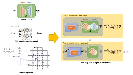
AMS Circuit Design Optimization Technique Based on ANN Regression Model With VAE Structure
View in IEEE Xplore
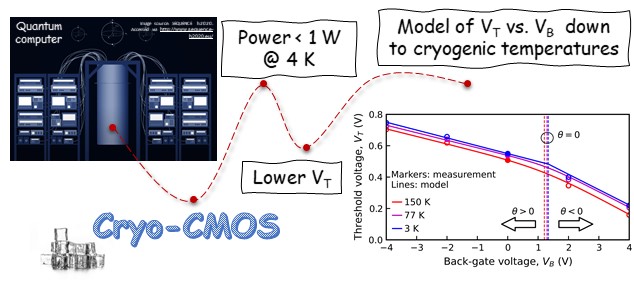
Novel Approach to FDSOI Threshold Voltage Model Validated at Cryogenic Temperatures
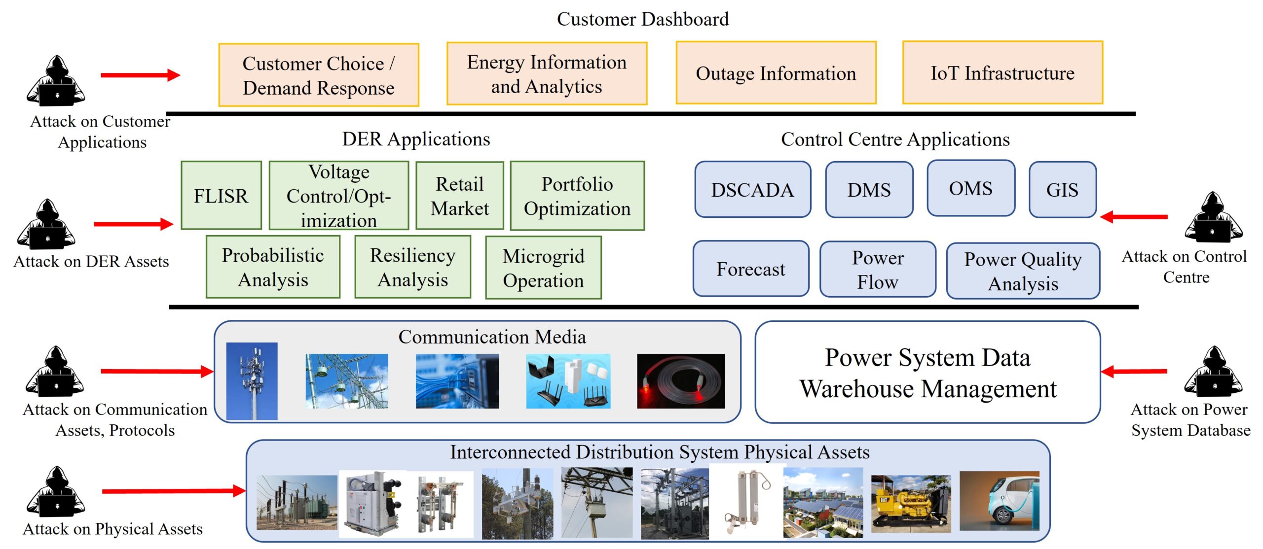
On the Cyber-Physical Needs of DER-Based Voltage Control/Optimization Algorithms in Active Distribution Network
Submission guidelines.
© 2024 IEEE - All rights reserved. Use of this website signifies your agreement to the IEEE TERMS AND CONDITIONS.
A not-for-profit organization, IEEE is the world’s largest technical professional organization dedicated to advancing technology for the benefit of humanity.
AWARD RULES:
NO PURCHASE NECESSARY TO ENTER OR WIN. A PURCHASE WILL NOT INCREASE YOUR CHANCES OF WINNING.
These rules apply to the “2024 IEEE Access Best Video Award Part 1″ (the “Award”).
- Sponsor: The Sponsor of the Award is The Institute of Electrical and Electronics Engineers, Incorporated (“IEEE”) on behalf of IEEE Access , 445 Hoes Lane, Piscataway, NJ 08854-4141 USA (“Sponsor”).
- Eligibility: Award is open to residents of the United States of America and other countries, where permitted by local law, who are the age of eighteen (18) and older. Employees of Sponsor, its agents, affiliates and their immediate families are not eligible to enter Award. The Award is subject to all applicable state, local, federal and national laws and regulations. Entrants may be subject to rules imposed by their institution or employer relative to their participation in Awards and should check with their institution or employer for any relevant policies. Void in locations and countries where prohibited by law.
- Agreement to Official Rules : By participating in this Award, entrants agree to abide by the terms and conditions thereof as established by Sponsor. Sponsor reserves the right to alter any of these Official Rules at any time and for any reason. All decisions made by Sponsor concerning the Award including, but not limited to the cancellation of the Award, shall be final and at its sole discretion.
- How to Enter: This Award opens on January 1, 2024 at 12:00 AM ET and all entries must be received by 11:59 PM ET on June 30, 2024 (“Promotional Period”).
Entrant must submit a video with an article submission to IEEE Access . The video submission must clearly be relevant to the submitted manuscript. Only videos that accompany an article that is accepted for publication in IEEE Access will qualify. The video may be simulations, demonstrations, or interviews with other experts, for example. Your video file should not exceed 100 MB.
Entrants can enter the Award during Promotional Period through the following method:
- The IEEE Author Portal : Entrants can upload their video entries while submitting their article through the IEEE Author Portal submission site .
- Review and Complete the Terms and Conditions: After submitting your manuscript and video through the IEEE Author Portal, entrants should then review and sign the Terms and Conditions .
Entrants who have already submitted a manuscript to IEEE Access without a video can still submit a video for inclusion in this Award so long as the video is submitted within 7 days of the article submission date. The video can be submitted via email to the article administrator. All videos must undergo peer review and be accepted along with the article submission. Videos may not be submitted after an article has already been accepted for publication.
The criteria for an article to be accepted for publication in IEEE Access are:
- The article must be original writing that enhances the existing body of knowledge in the given subject area. Original review articles and surveys are acceptable even if new data/concepts are not presented.
- Results reported must not have been submitted or published elsewhere (although expanded versions of conference publications are eligible for submission).
- Experiments, statistics, and other analyses must be performed to a high technical standard and are described in sufficient detail.
- Conclusions must be presented in an appropriate fashion and are supported by the data.
- The article must be written in standard English with correct grammar.
- Appropriate references to related prior published works must be included.
- The article must fall within the scope of IEEE Access
- Must be in compliance with the IEEE PSPB Operations Manual.
- Completion of the required IEEE intellectual property documents for publication.
- At the discretion of the IEEE Access Editor-in-Chief.
- Disqualification: The following items will disqualify a video from being considered a valid submission:
- The video is not original work.
- A video that is not accompanied with an article submission.
- The article and/or video is rejected during the peer review process.
- The article and/or video topic does not fit into the scope of IEEE Access .
- The article and/or do not follow the criteria for publication in IEEE Access .
- Videos posted in a comment on IEEE Xplore .
- Content is off-topic, offensive, obscene, indecent, abusive or threatening to others.
- Infringes the copyright, trademark or other right of any third party.
- Uploads viruses or other contaminating or destructive features.
- Is in violation of any applicable laws or regulations.
- Is not in English.
- Is not provided within the designated submission time.
- Entrant does not agree and sign the Terms and Conditions document.
Entries must be original. Entries that copy other entries, or the intellectual property of anyone other than the Entrant, may be removed by Sponsor and the Entrant may be disqualified. Sponsor reserves the right to remove any entry and disqualify any Entrant if the entry is deemed, in Sponsor’s sole discretion, to be inappropriate.
- Entrant’s Warranty and Authorization to Sponsor: By entering the Award, entrants warrant and represent that the Award Entry has been created and submitted by the Entrant. Entrant certifies that they have the ability to use any image, text, video, or other intellectual property they may upload and that Entrant has obtained all necessary permissions. IEEE shall not indemnify Entrant for any infringement, violation of publicity rights, or other civil or criminal violations. Entrant agrees to hold IEEE harmless for all actions related to the submission of an Entry. Entrants further represent and warrant, if they reside outside of the United States of America, that their participation in this Award and acceptance of a prize will not violate their local laws.
- Intellectual Property Rights: Entrant grants Sponsor an irrevocable, worldwide, royalty free license to use, reproduce, distribute, and display the Entry for any lawful purpose in all media whether now known or hereinafter created. This may include, but is not limited to, the IEEE A ccess website, the IEEE Access YouTube channel, the IEEE Access IEEE TV channel, IEEE Access social media sites (LinkedIn, Facebook, Twitter, IEEE Access Collabratec Community), and the IEEE Access Xplore page. Facebook/Twitter/Microsite usernames will not be used in any promotional and advertising materials without the Entrants’ expressed approval.
- Number of Prizes Available, Prizes, Approximate Retail Value and Odds of winning Prizes: Two (2) promotional prizes of $350 USD Amazon gift cards. One (1) grand prize of a $500 USD Amazon gift card. Prizes will be distributed to the winners after the selection of winners is announced. Odds of winning a prize depend on the number of eligible entries received during the Promotional Period. Only the corresponding author of the submitted manuscript will receive the prize.
The grand prize winner may, at Sponsor’ discretion, have his/her article and video highlighted in media such as the IEEE Access Xplore page and the IEEE Access social media sites.
The prize(s) for the Award are being sponsored by IEEE. No cash in lieu of prize or substitution of prize permitted, except that Sponsor reserves the right to substitute a prize or prize component of equal or greater value in its sole discretion for any reason at time of award. Sponsor shall not be responsible for service obligations or warranty (if any) in relation to the prize(s). Prize may not be transferred prior to award. All other expenses associated with use of the prize, including, but not limited to local, state, or federal taxes on the Prize, are the sole responsibility of the winner. Winner(s) understand that delivery of a prize may be void where prohibited by law and agrees that Sponsor shall have no obligation to substitute an alternate prize when so prohibited. Amazon is not a sponsor or affiliated with this Award.
- Selection of Winners: Promotional prize winners will be selected based on entries received during the Promotional Period. The sponsor will utilize an Editorial Panel to vote on the best video submissions. Editorial Panel members are not eligible to participate in the Award. Entries will be ranked based on three (3) criteria:
- Presentation of Technical Content
- Quality of Video
Upon selecting a winner, the Sponsor will notify the winner via email. All potential winners will be notified via their email provided to the sponsor. Potential winners will have five (5) business days to respond after receiving initial prize notification or the prize may be forfeited and awarded to an alternate winner. Potential winners may be required to sign an affidavit of eligibility, a liability release, and a publicity release. If requested, these documents must be completed, signed, and returned within ten (10) business days from the date of issuance or the prize will be forfeited and may be awarded to an alternate winner. If prize or prize notification is returned as undeliverable or in the event of noncompliance with these Official Rules, prize will be forfeited and may be awarded to an alternate winner.
- General Prize Restrictions: No prize substitutions or transfer of prize permitted, except by the Sponsor. Import/Export taxes, VAT and country taxes on prizes are the sole responsibility of winners. Acceptance of a prize constitutes permission for the Sponsor and its designees to use winner’s name and likeness for advertising, promotional and other purposes in any and all media now and hereafter known without additional compensation unless prohibited by law. Winner acknowledges that neither Sponsor, Award Entities nor their directors, employees, or agents, have made nor are in any manner responsible or liable for any warranty, representation, or guarantee, express or implied, in fact or in law, relative to any prize, including but not limited to its quality, mechanical condition or fitness for a particular purpose. Any and all warranties and/or guarantees on a prize (if any) are subject to the respective manufacturers’ terms therefor, and winners agree to look solely to such manufacturers for any such warranty and/or guarantee.
11.Release, Publicity, and Privacy : By receipt of the Prize and/or, if requested, by signing an affidavit of eligibility and liability/publicity release, the Prize Winner consents to the use of his or her name, likeness, business name and address by Sponsor for advertising and promotional purposes, including but not limited to on Sponsor’s social media pages, without any additional compensation, except where prohibited. No entries will be returned. All entries become the property of Sponsor. The Prize Winner agrees to release and hold harmless Sponsor and its officers, directors, employees, affiliated companies, agents, successors and assigns from and against any claim or cause of action arising out of participation in the Award.
Sponsor assumes no responsibility for computer system, hardware, software or program malfunctions or other errors, failures, delayed computer transactions or network connections that are human or technical in nature, or for damaged, lost, late, illegible or misdirected entries; technical, hardware, software, electronic or telephone failures of any kind; lost or unavailable network connections; fraudulent, incomplete, garbled or delayed computer transmissions whether caused by Sponsor, the users, or by any of the equipment or programming associated with or utilized in this Award; or by any technical or human error that may occur in the processing of submissions or downloading, that may limit, delay or prevent an entrant’s ability to participate in the Award.
Sponsor reserves the right, in its sole discretion, to cancel or suspend this Award and award a prize from entries received up to the time of termination or suspension should virus, bugs or other causes beyond Sponsor’s control, unauthorized human intervention, malfunction, computer problems, phone line or network hardware or software malfunction, which, in the sole opinion of Sponsor, corrupt, compromise or materially affect the administration, fairness, security or proper play of the Award or proper submission of entries. Sponsor is not liable for any loss, injury or damage caused, whether directly or indirectly, in whole or in part, from downloading data or otherwise participating in this Award.
Representations and Warranties Regarding Entries: By submitting an Entry, you represent and warrant that your Entry does not and shall not comprise, contain, or describe, as determined in Sponsor’s sole discretion: (A) false statements or any misrepresentations of your affiliation with a person or entity; (B) personally identifying information about you or any other person; (C) statements or other content that is false, deceptive, misleading, scandalous, indecent, obscene, unlawful, defamatory, libelous, fraudulent, tortious, threatening, harassing, hateful, degrading, intimidating, or racially or ethnically offensive; (D) conduct that could be considered a criminal offense, could give rise to criminal or civil liability, or could violate any law; (E) any advertising, promotion or other solicitation, or any third party brand name or trademark; or (F) any virus, worm, Trojan horse, or other harmful code or component. By submitting an Entry, you represent and warrant that you own the full rights to the Entry and have obtained any and all necessary consents, permissions, approvals and licenses to submit the Entry and comply with all of these Official Rules, and that the submitted Entry is your sole original work, has not been previously published, released or distributed, and does not infringe any third-party rights or violate any laws or regulations.
12.Disputes: EACH ENTRANT AGREES THAT: (1) ANY AND ALL DISPUTES, CLAIMS, AND CAUSES OF ACTION ARISING OUT OF OR IN CONNECTION WITH THIS AWARD, OR ANY PRIZES AWARDED, SHALL BE RESOLVED INDIVIDUALLY, WITHOUT RESORTING TO ANY FORM OF CLASS ACTION, PURSUANT TO ARBITRATION CONDUCTED UNDER THE COMMERCIAL ARBITRATION RULES OF THE AMERICAN ARBITRATION ASSOCIATION THEN IN EFFECT, (2) ANY AND ALL CLAIMS, JUDGMENTS AND AWARDS SHALL BE LIMITED TO ACTUAL OUT-OF-POCKET COSTS INCURRED, INCLUDING COSTS ASSOCIATED WITH ENTERING THIS AWARD, BUT IN NO EVENT ATTORNEYS’ FEES; AND (3) UNDER NO CIRCUMSTANCES WILL ANY ENTRANT BE PERMITTED TO OBTAIN AWARDS FOR, AND ENTRANT HEREBY WAIVES ALL RIGHTS TO CLAIM, PUNITIVE, INCIDENTAL, AND CONSEQUENTIAL DAMAGES, AND ANY OTHER DAMAGES, OTHER THAN FOR ACTUAL OUT-OF-POCKET EXPENSES, AND ANY AND ALL RIGHTS TO HAVE DAMAGES MULTIPLIED OR OTHERWISE INCREASED. ALL ISSUES AND QUESTIONS CONCERNING THE CONSTRUCTION, VALIDITY, INTERPRETATION AND ENFORCEABILITY OF THESE OFFICIAL RULES, OR THE RIGHTS AND OBLIGATIONS OF ENTRANT AND SPONSOR IN CONNECTION WITH THE AWARD, SHALL BE GOVERNED BY, AND CONSTRUED IN ACCORDANCE WITH, THE LAWS OF THE STATE OF NEW JERSEY, WITHOUT GIVING EFFECT TO ANY CHOICE OF LAW OR CONFLICT OF LAW, RULES OR PROVISIONS (WHETHER OF THE STATE OF NEW JERSEY OR ANY OTHER JURISDICTION) THAT WOULD CAUSE THE APPLICATION OF THE LAWS OF ANY JURISDICTION OTHER THAN THE STATE OF NEW JERSEY. SPONSOR IS NOT RESPONSIBLE FOR ANY TYPOGRAPHICAL OR OTHER ERROR IN THE PRINTING OF THE OFFER OR ADMINISTRATION OF THE AWARD OR IN THE ANNOUNCEMENT OF THE PRIZES.
- Limitation of Liability: The Sponsor, Award Entities and their respective parents, affiliates, divisions, licensees, subsidiaries, and advertising and promotion agencies, and each of the foregoing entities’ respective employees, officers, directors, shareholders and agents (the “Released Parties”) are not responsible for incorrect or inaccurate transfer of entry information, human error, technical malfunction, lost/delayed data transmissions, omission, interruption, deletion, defect, line failures of any telephone network, computer equipment, software or any combination thereof, inability to access web sites, damage to a user’s computer system (hardware and/or software) due to participation in this Award or any other problem or error that may occur. By entering, participants agree to release and hold harmless the Released Parties from and against any and all claims, actions and/or liability for injuries, loss or damage of any kind arising from or in connection with participation in and/or liability for injuries, loss or damage of any kind, to person or property, arising from or in connection with participation in and/or entry into this Award, participation is any Award-related activity or use of any prize won. Entry materials that have been tampered with or altered are void. If for any reason this Award is not capable of running as planned, or if this Award or any website associated therewith (or any portion thereof) becomes corrupted or does not allow the proper playing of this Award and processing of entries per these rules, or if infection by computer virus, bugs, tampering, unauthorized intervention, affect the administration, security, fairness, integrity, or proper conduct of this Award, Sponsor reserves the right, at its sole discretion, to disqualify any individual implicated in such action, and/or to cancel, terminate, modify or suspend this Award or any portion thereof, or to amend these rules without notice. In the event of a dispute as to who submitted an online entry, the entry will be deemed submitted by the authorized account holder the email address submitted at the time of entry. “Authorized Account Holder” is defined as the person assigned to an email address by an Internet access provider, online service provider or other organization responsible for assigning email addresses for the domain associated with the email address in question. Any attempt by an entrant or any other individual to deliberately damage any web site or undermine the legitimate operation of the Award is a violation of criminal and civil laws and should such an attempt be made, the Sponsor reserves the right to seek damages and other remedies from any such person to the fullest extent permitted by law. This Award is governed by the laws of the State of New Jersey and all entrants hereby submit to the exclusive jurisdiction of federal or state courts located in the State of New Jersey for the resolution of all claims and disputes. Facebook, LinkedIn, Twitter, G+, YouTube, IEEE Xplore , and IEEE TV are not sponsors nor affiliated with this Award.
- Award Results and Official Rules: To obtain the identity of the prize winner and/or a copy of these Official Rules, send a self-addressed stamped envelope to Kimberly Rybczynski, IEEE, 445 Hoes Lane, Piscataway, NJ 08854-4141 USA.

An official website of the United States government
The .gov means it’s official. Federal government websites often end in .gov or .mil. Before sharing sensitive information, make sure you’re on a federal government site.
The site is secure. The https:// ensures that you are connecting to the official website and that any information you provide is encrypted and transmitted securely.
- Publications
- Account settings
Preview improvements coming to the PMC website in October 2024. Learn More or Try it out now .
- Advanced Search
- Journal List
- Sensors (Basel)
Study and Investigation on 5G Technology: A Systematic Review
Ramraj dangi.
1 School of Computing Science and Engineering, VIT University Bhopal, Bhopal 466114, India; [email protected] (R.D.); [email protected] (P.L.)
Praveen Lalwani
Gaurav choudhary.
2 Department of Applied Mathematics and Computer Science, Technical University of Denmark, 2800 Lyngby, Denmark; moc.liamg@7777yrahduohcvaruag
3 Department of Information Security Engineering, Soonchunhyang University, Asan-si 31538, Korea
Giovanni Pau
4 Faculty of Engineering and Architecture, Kore University of Enna, 94100 Enna, Italy; [email protected]
Associated Data
Not applicable.
In wireless communication, Fifth Generation (5G) Technology is a recent generation of mobile networks. In this paper, evaluations in the field of mobile communication technology are presented. In each evolution, multiple challenges were faced that were captured with the help of next-generation mobile networks. Among all the previously existing mobile networks, 5G provides a high-speed internet facility, anytime, anywhere, for everyone. 5G is slightly different due to its novel features such as interconnecting people, controlling devices, objects, and machines. 5G mobile system will bring diverse levels of performance and capability, which will serve as new user experiences and connect new enterprises. Therefore, it is essential to know where the enterprise can utilize the benefits of 5G. In this research article, it was observed that extensive research and analysis unfolds different aspects, namely, millimeter wave (mmWave), massive multiple-input and multiple-output (Massive-MIMO), small cell, mobile edge computing (MEC), beamforming, different antenna technology, etc. This article’s main aim is to highlight some of the most recent enhancements made towards the 5G mobile system and discuss its future research objectives.
1. Introduction
Most recently, in three decades, rapid growth was marked in the field of wireless communication concerning the transition of 1G to 4G [ 1 , 2 ]. The main motto behind this research was the requirements of high bandwidth and very low latency. 5G provides a high data rate, improved quality of service (QoS), low-latency, high coverage, high reliability, and economically affordable services. 5G delivers services categorized into three categories: (1) Extreme mobile broadband (eMBB). It is a nonstandalone architecture that offers high-speed internet connectivity, greater bandwidth, moderate latency, UltraHD streaming videos, virtual reality and augmented reality (AR/VR) media, and many more. (2) Massive machine type communication (eMTC), 3GPP releases it in its 13th specification. It provides long-range and broadband machine-type communication at a very cost-effective price with less power consumption. eMTC brings a high data rate service, low power, extended coverage via less device complexity through mobile carriers for IoT applications. (3) ultra-reliable low latency communication (URLLC) offers low-latency and ultra-high reliability, rich quality of service (QoS), which is not possible with traditional mobile network architecture. URLLC is designed for on-demand real-time interaction such as remote surgery, vehicle to vehicle (V2V) communication, industry 4.0, smart grids, intelligent transport system, etc. [ 3 ].
1.1. Evolution from 1G to 5G
First generation (1G): 1G cell phone was launched between the 1970s and 80s, based on analog technology, which works just like a landline phone. It suffers in various ways, such as poor battery life, voice quality, and dropped calls. In 1G, the maximum achievable speed was 2.4 Kbps.
Second Generation (2G): In 2G, the first digital system was offered in 1991, providing improved mobile voice communication over 1G. In addition, Code-Division Multiple Access (CDMA) and Global System for Mobile (GSM) concepts were also discussed. In 2G, the maximum achievable speed was 1 Mpbs.
Third Generation (3G): When technology ventured from 2G GSM frameworks into 3G universal mobile telecommunication system (UMTS) framework, users encountered higher system speed and quicker download speed making constant video calls. 3G was the first mobile broadband system that was formed to provide the voice with some multimedia. The technology behind 3G was high-speed packet access (HSPA/HSPA+). 3G used MIMO for multiplying the power of the wireless network, and it also used packet switching for fast data transmission.
Fourth Generation (4G): It is purely mobile broadband standard. In digital mobile communication, it was observed information rate that upgraded from 20 to 60 Mbps in 4G [ 4 ]. It works on LTE and WiMAX technologies, as well as provides wider bandwidth up to 100 Mhz. It was launched in 2010.
Fourth Generation LTE-A (4.5G): It is an advanced version of standard 4G LTE. LTE-A uses MIMO technology to combine multiple antennas for both transmitters as well as a receiver. Using MIMO, multiple signals and multiple antennas can work simultaneously, making LTE-A three times faster than standard 4G. LTE-A offered an improved system limit, decreased deferral in the application server, access triple traffic (Data, Voice, and Video) wirelessly at any time anywhere in the world.LTE-A delivers speeds of over 42 Mbps and up to 90 Mbps.
Fifth Generation (5G): 5G is a pillar of digital transformation; it is a real improvement on all the previous mobile generation networks. 5G brings three different services for end user like Extreme mobile broadband (eMBB). It offers high-speed internet connectivity, greater bandwidth, moderate latency, UltraHD streaming videos, virtual reality and augmented reality (AR/VR) media, and many more. Massive machine type communication (eMTC), it provides long-range and broadband machine-type communication at a very cost-effective price with less power consumption. eMTC brings a high data rate service, low power, extended coverage via less device complexity through mobile carriers for IoT applications. Ultra-reliable low latency communication (URLLC) offers low-latency and ultra-high reliability, rich quality of service (QoS), which is not possible with traditional mobile network architecture. URLLC is designed for on-demand real-time interaction such as remote surgery, vehicle to vehicle (V2V) communication, industry 4.0, smart grids, intelligent transport system, etc. 5G faster than 4G and offers remote-controlled operation over a reliable network with zero delays. It provides down-link maximum throughput of up to 20 Gbps. In addition, 5G also supports 4G WWWW (4th Generation World Wide Wireless Web) [ 5 ] and is based on Internet protocol version 6 (IPv6) protocol. 5G provides unlimited internet connection at your convenience, anytime, anywhere with extremely high speed, high throughput, low-latency, higher reliability and scalability, and energy-efficient mobile communication technology [ 6 ]. 5G mainly divided in two parts 6 GHz 5G and Millimeter wave(mmWave) 5G.
6 GHz is a mid frequency band which works as a mid point between capacity and coverage to offer perfect environment for 5G connectivity. 6 GHz spectrum will provide high bandwidth with improved network performance. It offers continuous channels that will reduce the need for network densification when mid-band spectrum is not available and it makes 5G connectivity affordable at anytime, anywhere for everyone.
mmWave is an essential technology of 5G network which build high performance network. 5G mmWave offer diverse services that is why all network providers should add on this technology in their 5G deployment planning. There are lots of service providers who deployed 5G mmWave, and their simulation result shows that 5G mmwave is a far less used spectrum. It provides very high speed wireless communication and it also offers ultra-wide bandwidth for next generation mobile network.
The evolution of wireless mobile technologies are presented in Table 1 . The abbreviations used in this paper are mentioned in Table 2 .
Summary of Mobile Technology.
| Generations | Access Techniques | Transmission Techniques | Error Correction Mechanism | Data Rate | Frequency Band | Bandwidth | Application | Description |
|---|---|---|---|---|---|---|---|---|
| 1G | FDMA, AMPS | Circuit Switching | NA | 2.4 kbps | 800 MHz | Analog | Voice | Let us talk to each other |
| 2G | GSM, TDMA, CDMA | Circuit Switching | NA | 10 kbps | 800 MHz, 900 MHz, 1800 MHz, 1900 MHz | 25 MHz | Voice and Data | Let us send messages and travel with improved data services |
| 3G | WCDMA, UMTS, CDMA 2000, HSUPA/HSDPA | Circuit and Packet Switching | Turbo Codes | 384 kbps to 5 Mbps | 800 MHz, 850 MHz, 900 MHz, 1800 MHz, 1900 MHz, 2100 MHz | 25 MHz | Voice, Data, and Video Calling | Let us experience surfing internet and unleashing mobile applications |
| 4G | LTEA, OFDMA, SCFDMA, WIMAX | Packet switching | Turbo Codes | 100 Mbps to 200 Mbps | 2.3 GHz, 2.5 GHz and 3.5 GHz initially | 100 MHz | Voice, Data, Video Calling, HD Television, and Online Gaming. | Let’s share voice and data over fast broadband internet based on unified networks architectures and IP protocols |
| 5G | BDMA, NOMA, FBMC | Packet Switching | LDPC | 10 Gbps to 50 Gbps | 1.8 GHz, 2.6 GHz and 30–300 GHz | 30–300 GHz | Voice, Data, Video Calling, Ultra HD video, Virtual Reality applications | Expanded the broadband wireless services beyond mobile internet with IOT and V2X. |
Table of Notations and Abbreviations.
| Abbreviation | Full Form | Abbreviation | Full Form |
|---|---|---|---|
| AMF | Access and Mobility Management Function | M2M | Machine-to-Machine |
| AT&T | American Telephone and Telegraph | mmWave | millimeter wave |
| BS | Base Station | NGMN | Next Generation Mobile Networks |
| CDMA | Code-Division Multiple Access | NOMA | Non-Orthogonal Multiple Access |
| CSI | Channel State Information | NFV | Network Functions Virtualization |
| D2D | Device to Device | OFDM | Orthogonal Frequency Division Multiplexing |
| EE | Energy Efficiency | OMA | Orthogonal Multiple Access |
| EMBB | Enhanced mobile broadband: | QoS | Quality of Service |
| ETSI | European Telecommunications Standards Institute | RNN | Recurrent Neural Network |
| eMTC | Massive Machine Type Communication | SDN | Software-Defined Networking |
| FDMA | Frequency Division Multiple Access | SC | Superposition Coding |
| FDD | Frequency Division Duplex | SIC | Successive Interference Cancellation |
| GSM | Global System for Mobile | TDMA | Time Division Multiple Access |
| HSPA | High Speed Packet Access | TDD | Time Division Duplex |
| IoT | Internet of Things | UE | User Equipment |
| IETF | Internet Engineering Task Force | URLLC | Ultra Reliable Low Latency Communication |
| LTE | Long-Term Evolution | UMTC | Universal Mobile Telecommunications System |
| ML | Machine Learning | V2V | Vehicle to Vehicle |
| MIMO | Multiple Input Multiple Output | V2X | Vehicle to Everything |
1.2. Key Contributions
The objective of this survey is to provide a detailed guide of 5G key technologies, methods to researchers, and to help with understanding how the recent works addressed 5G problems and developed solutions to tackle the 5G challenges; i.e., what are new methods that must be applied and how can they solve problems? Highlights of the research article are as follows.
- This survey focused on the recent trends and development in the era of 5G and novel contributions by the researcher community and discussed technical details on essential aspects of the 5G advancement.
- In this paper, the evolution of the mobile network from 1G to 5G is presented. In addition, the growth of mobile communication under different attributes is also discussed.
- This paper covers the emerging applications and research groups working on 5G & different research areas in 5G wireless communication network with a descriptive taxonomy.
- This survey discusses the current vision of the 5G networks, advantages, applications, key technologies, and key features. Furthermore, machine learning prospects are also explored with the emerging requirements in the 5G era. The article also focused on technical aspects of 5G IoT Based approaches and optimization techniques for 5G.
- we provide an extensive overview and recent advancement of emerging technologies of 5G mobile network, namely, MIMO, Non-Orthogonal Multiple Access (NOMA), mmWave, Internet of Things (IoT), Machine Learning (ML), and optimization. Also, a technical summary is discussed by highlighting the context of current approaches and corresponding challenges.
- Security challenges and considerations while developing 5G technology are discussed.
- Finally, the paper concludes with the future directives.
The existing survey focused on architecture, key concepts, and implementation challenges and issues. In contrast, this survey covers the state-of-the-art techniques as well as corresponding recent novel developments by researchers. Various recent significant papers are discussed with the key technologies accelerating the development and production of 5G products.
2. Existing Surveys and Their Applicability
In this paper, a detailed survey on various technologies of 5G networks is presented. Various researchers have worked on different technologies of 5G networks. In this section, Table 3 gives a tabular representation of existing surveys of 5G networks. Massive MIMO, NOMA, small cell, mmWave, beamforming, and MEC are the six main pillars that helped to implement 5G networks in real life.
A comparative overview of existing surveys on different technologies of 5G networks.
| Authors& References | MIMO | NOMA | MmWave | 5G IOT | 5G ML | Small Cell | Beamforming | MEC | 5G Optimization |
|---|---|---|---|---|---|---|---|---|---|
| Chataut and Akl [ ] | Yes | - | Yes | - | - | - | Yes | - | - |
| Prasad et al. [ ] | Yes | - | Yes | - | - | - | - | - | - |
| Kiani and Nsari [ ] | - | Yes | - | - | - | - | - | Yes | - |
| Timotheou and Krikidis [ ] | - | Yes | - | - | - | - | - | - | Yes |
| Yong Niu et al. [ ] | - | - | Yes | - | - | Yes | - | - | - |
| Qiao et al. [ ] | - | - | Yes | - | - | - | - | - | Yes |
| Ramesh et al. [ ] | Yes | - | Yes | - | - | - | - | - | - |
| Khurpade et al. [ ] | Yes | Yes | - | Yes | - | - | - | - | - |
| Bega et al. [ ] | - | - | - | - | Yes | - | - | - | Yes |
| Abrol and jha [ ] | - | - | - | - | - | Yes | - | - | Yes |
| Wei et al. [ ] | - | Yes | - | - | - | - | - | - | |
| Jakob Hoydis et al. [ ] | - | - | - | - | - | Yes | - | - | - |
| Papadopoulos et al. [ ] | Yes | - | - | - | - | - | Yes | - | - |
| Shweta Rajoria et al. [ ] | Yes | - | Yes | - | - | Yes | Yes | - | - |
| Demosthenes Vouyioukas [ ] | Yes | - | - | - | - | - | Yes | - | - |
| Al-Imari et al. [ ] | - | Yes | Yes | - | - | - | - | - | - |
| Michael Till Beck et al. [ ] | - | - | - | - | - | - | Yes | - | |
| Shuo Wang et al. [ ] | - | - | - | - | - | - | Yes | - | |
| Gupta and Jha [ ] | Yes | - | - | - | - | Yes | - | Yes | - |
| Our Survey | Yes | Yes | Yes | Yes | Yes | Yes | Yes | Yes | Yes |
2.1. Limitations of Existing Surveys
The existing survey focused on architecture, key concepts, and implementation challenges and issues. The numerous current surveys focused on various 5G technologies with different parameters, and the authors did not cover all the technologies of the 5G network in detail with challenges and recent advancements. Few authors worked on MIMO (Non-Orthogonal Multiple Access) NOMA, MEC, small cell technologies. In contrast, some others worked on beamforming, Millimeter-wave (mmWave). But the existing survey did not cover all the technologies of the 5G network from a research and advancement perspective. No detailed survey is available in the market covering all the 5G network technologies and currently published research trade-offs. So, our main aim is to give a detailed study of all the technologies working on the 5G network. In contrast, this survey covers the state-of-the-art techniques as well as corresponding recent novel developments by researchers. Various recent significant papers are discussed with the key technologies accelerating the development and production of 5G products. This survey article collected key information about 5G technology and recent advancements, and it can be a kind of a guide for the reader. This survey provides an umbrella approach to bring multiple solutions and recent improvements in a single place to accelerate the 5G research with the latest key enabling solutions and reviews. A systematic layout representation of the survey in Figure 1 . We provide a state-of-the-art comparative overview of the existing surveys on different technologies of 5G networks in Table 3 .

Systematic layout representation of survey.
2.2. Article Organization
This article is organized under the following sections. Section 2 presents existing surveys and their applicability. In Section 3 , the preliminaries of 5G technology are presented. In Section 4 , recent advances of 5G technology based on Massive MIMO, NOMA, Millimeter Wave, 5G with IoT, machine learning for 5G, and Optimization in 5G are provided. In Section 5 , a description of novel 5G features over 4G is provided. Section 6 covered all the security concerns of the 5G network. Section 7 , 5G technology based on above-stated challenges summarize in tabular form. Finally, Section 8 and Section 9 conclude the study, which paves the path for future research.
3. Preliminary Section
3.1. emerging 5g paradigms and its features.
5G provides very high speed, low latency, and highly salable connectivity between multiple devices and IoT worldwide. 5G will provide a very flexible model to develop a modern generation of applications and industry goals [ 26 , 27 ]. There are many services offered by 5G network architecture are stated below:
Massive machine to machine communications: 5G offers novel, massive machine-to-machine communications [ 28 ], also known as the IoT [ 29 ], that provide connectivity between lots of machines without any involvement of humans. This service enhances the applications of 5G and provides connectivity between agriculture, construction, and industries [ 30 ].
Ultra-reliable low latency communications (URLLC): This service offers real-time management of machines, high-speed vehicle-to-vehicle connectivity, industrial connectivity and security principles, and highly secure transport system, and multiple autonomous actions. Low latency communications also clear up a different area where remote medical care, procedures, and operation are all achievable [ 31 ].
Enhanced mobile broadband: Enhance mobile broadband is an important use case of 5G system, which uses massive MIMO antenna, mmWave, beamforming techniques to offer very high-speed connectivity across a wide range of areas [ 32 ].
For communities: 5G provides a very flexible internet connection between lots of machines to make smart homes, smart schools, smart laboratories, safer and smart automobiles, and good health care centers [ 33 ].
For businesses and industry: As 5G works on higher spectrum ranges from 24 to 100 GHz. This higher frequency range provides secure low latency communication and high-speed wireless connectivity between IoT devices and industry 4.0, which opens a market for end-users to enhance their business models [ 34 ].
New and Emerging technologies: As 5G came up with many new technologies like beamforming, massive MIMO, mmWave, small cell, NOMA, MEC, and network slicing, it introduced many new features to the market. Like virtual reality (VR), users can experience the physical presence of people who are millions of kilometers away from them. Many new technologies like smart homes, smart workplaces, smart schools, smart sports academy also came into the market with this 5G Mobile network model [ 35 ].
3.2. Commercial Service Providers of 5G
5G provides high-speed internet browsing, streaming, and downloading with very high reliability and low latency. 5G network will change your working style, and it will increase new business opportunities and provide innovations that we cannot imagine. This section covers top service providers of 5G network [ 36 , 37 ].
Ericsson: Ericsson is a Swedish multinational networking and telecommunications company, investing around 25.62 billion USD in 5G network, which makes it the biggest telecommunication company. It claims that it is the only company working on all the continents to make the 5G network a global standard for the next generation wireless communication. Ericsson developed the first 5G radio prototype that enables the operators to set up the live field trials in their network, which helps operators understand how 5G reacts. It plays a vital role in the development of 5G hardware. It currently provides 5G services in over 27 countries with content providers like China Mobile, GCI, LGU+, AT&T, Rogers, and many more. It has 100 commercial agreements with different operators as of 2020.
Verizon: It is American multinational telecommunication which was founded in 1983. Verizon started offering 5G services in April 2020, and by December 2020, it has actively provided 5G services in 30 cities of the USA. They planned that by the end of 2021, they would deploy 5G in 30 more new cities. Verizon deployed a 5G network on mmWave, a very high band spectrum between 30 to 300 GHz. As it is a significantly less used spectrum, it provides very high-speed wireless communication. MmWave offers ultra-wide bandwidth for next-generation mobile networks. MmWave is a faster and high-band spectrum that has a limited range. Verizon planned to increase its number of 5G cells by 500% by 2020. Verizon also has an ultra wide-band flagship 5G service which is the best 5G service that increases the market price of Verizon.
Nokia: Nokia is a Finnish multinational telecommunications company which was founded in 1865. Nokia is one of the companies which adopted 5G technology very early. It is developing, researching, and building partnerships with various 5G renders to offer 5G communication as soon as possible. Nokia collaborated with Deutsche Telekom and Hamburg Port Authority and provided them 8000-hectare site for their 5G MoNArch project. Nokia is the only company that supplies 5G technology to all the operators of different countries like AT&T, Sprint, T-Mobile US and Verizon in the USA, Korea Telecom, LG U+ and SK Telecom in South Korea and NTT DOCOMO, KDDI, and SoftBank in Japan. Presently, Nokia has around 150+ agreements and 29 live networks all over the world. Nokia is continuously working hard on 5G technology to expand 5G networks all over the globe.
AT&T: AT&T is an American multinational company that was the first to deploy a 5G network in reality in 2018. They built a gigabit 5G network connection in Waco, TX, Kalamazoo, MI, and South Bend to achieve this. It is the first company that archives 1–2 gigabit per second speed in 2019. AT&T claims that it provides a 5G network connection among 225 million people worldwide by using a 6 GHz spectrum band.
T-Mobile: T-Mobile US (TMUS) is an American wireless network operator which was the first service provider that offers a real 5G nationwide network. The company knew that high-band 5G was not feasible nationwide, so they used a 600 MHz spectrum to build a significant portion of its 5G network. TMUS is planning that by 2024 they will double the total capacity and triple the full 5G capacity of T-Mobile and Sprint combined. The sprint buyout is helping T-Mobile move forward the company’s current market price to 129.98 USD.
Samsung: Samsung started their research in 5G technology in 2011. In 2013, Samsung successfully developed the world’s first adaptive array transceiver technology operating in the millimeter-wave Ka bands for cellular communications. Samsung provides several hundred times faster data transmission than standard 4G for core 5G mobile communication systems. The company achieved a lot of success in the next generation of technology, and it is considered one of the leading companies in the 5G domain.
Qualcomm: Qualcomm is an American multinational corporation in San Diego, California. It is also one of the leading company which is working on 5G chip. Qualcomm’s first 5G modem chip was announced in October 2016, and a prototype was demonstrated in October 2017. Qualcomm mainly focuses on building products while other companies talk about 5G; Qualcomm is building the technologies. According to one magazine, Qualcomm was working on three main areas of 5G networks. Firstly, radios that would use bandwidth from any network it has access to; secondly, creating more extensive ranges of spectrum by combining smaller pieces; and thirdly, a set of services for internet applications.
ZTE Corporation: ZTE Corporation was founded in 1985. It is a partially Chinese state-owned technology company that works in telecommunication. It was a leading company that worked on 4G LTE, and it is still maintaining its value and doing research and tests on 5G. It is the first company that proposed Pre5G technology with some series of solutions.
NEC Corporation: NEC Corporation is a Japanese multinational information technology and electronics corporation headquartered in Minato, Tokyo. ZTE also started their research on 5G, and they introduced a new business concept. NEC’s main aim is to develop 5G NR for the global mobile system and create secure and intelligent technologies to realize 5G services.
Cisco: Cisco is a USA networking hardware company that also sleeves up for 5G network. Cisco’s primary focus is to support 5G in three ways: Service—enable 5G services faster so all service providers can increase their business. Infrastructure—build 5G-oriented infrastructure to implement 5G more quickly. Automation—make a more scalable, flexible, and reliable 5G network. The companies know the importance of 5G, and they want to connect more than 30 billion devices in the next couple of years. Cisco intends to work on network hardening as it is a vital part of 5G network. Cisco used AI with deep learning to develop a 5G Security Architecture, enabling Secure Network Transformation.
3.3. 5G Research Groups
Many research groups from all over the world are working on a 5G wireless mobile network [ 38 ]. These groups are continuously working on various aspects of 5G. The list of those research groups are presented as follows: 5GNOW (5th Generation Non-Orthogonal Waveform for Asynchronous Signaling), NEWCOM (Network of Excellence in Wireless Communication), 5GIC (5G Innovation Center), NYU (New York University) Wireless, 5GPPP (5G Infrastructure Public-Private Partnership), EMPHATIC (Enhanced Multi-carrier Technology for Professional Adhoc and Cell-Based Communication), ETRI(Electronics and Telecommunication Research Institute), METIS (Mobile and wireless communication Enablers for the Twenty-twenty Information Society) [ 39 ]. The various research groups along with the research area are presented in Table 4 .
Research groups working on 5G mobile networks.
| Research Groups | Research Area | Description |
|---|---|---|
| METIS (Mobile and wireless communications Enablers for Twenty-twenty (2020) Information Society) | Working 5G Framework | METIS focused on RAN architecture and designed an air interface which evaluates data rates on peak hours, traffic load per region, traffic volume per user and actual client data rates. They have generate METIS published an article on February, 2015 in which they developed RAN architecture with simulation results. They design an air interface which evaluates data rates on peak hours, traffic load per region, traffic volume per user and actual client data rates.They have generate very less RAN latency under 1ms. They also introduced diverse RAN model and traffic flow in different situation like malls, offices, colleges and stadiums. |
| 5G PPP (5G Infrastructure Public Private Partnership) | Next generation mobile network communication, high speed Connectivity. | Fifth generation infrastructure public partnership project is a joint startup by two groups (European Commission and European ICT industry). 5G-PPP will provide various standards architectures, solutions and technologies for next generation mobile network in coming decade. The main motto behind 5G-PPP is that, through this project, European Commission wants to give their contribution in smart cities, e-health, intelligent transport, education, entertainment, and media. |
| 5GNOW (5th Generation Non-Orthogonal Waveforms for asynchronous signaling) | Non-orthogonal Multiple Access | 5GNOW’s is working on modulation and multiplexing techniques for next generation network. 5GNOW’s offers ultra-high reliability and ultra-low latency communication with visible waveform for 5G. 5GNOW’s also worked on acquiring time and frequency plane information of a signal using short term Fourier transform (STFT) |
| EMPhAtiC (Enhanced Multicarrier Technology for Professional Ad-Hoc and Cell-Based Communications) | MIMO Transmission | EMPhAtiC is working on MIMO transmission to develop a secure communication techniques with asynchronicity based on flexible filter bank and multihop. Recently they also launched MIMO based trans-receiver technique under frequency selective channels for Filter Bank Multi-Carrier (FBMC) |
| NEWCOM (Network of Excellence in Wireless Communications) | Advanced aspects of wireless communications | NEWCOM is working on energy efficiency, channel efficiency, multihop communication in wireless communication. Recently, they are working on cloud RAN, mobile broadband, local and distributed antenna techniques and multi-hop communication for 5G network. Finally, in their final research they give on result that QAM modulation schema, system bandwidth and resource block is used to process the base band. |
| NYU New York University Wireless | Millimeter Wave | NYU Wireless is research center working on wireless communication, sensors, networking and devices. In their recent research, NYU focuses on developing smaller and lighter antennas with directional beamforming to provide reliable wireless communication. |
| 5GIC 5G Innovation Centre | Decreasing network costs, Preallocation of resources according to user’s need, point-to-point communication, Highspeed connectivity. | 5GIC, is a UK’s research group, which is working on high-speed wireless communication. In their recent research they got 1Tbps speed in point-to-point wireless communication. Their main focus is on developing ultra-low latency app services. |
| ETRI (Electronics and Telecommunication Research Institute) | Device-to-device communication, MHN protocol stack | ETRI (Electronics and Telecommunication Research Institute), is a research group of Korea, which is focusing on improving the reliability of 5G network, device-to-device communication and MHN protocol stack. |
3.4. 5G Applications
5G is faster than 4G and offers remote-controlled operation over a reliable network with zero delays. It provides down-link maximum throughput of up to 20 Gbps. In addition, 5G also supports 4G WWWW (4th Generation World Wide Wireless Web) [ 5 ] and is based on Internet protocol version 6 (IPv6) protocol. 5G provides unlimited internet connection at your convenience, anytime, anywhere with extremely high speed, high throughput, low-latency, higher reliability, greater scalablility, and energy-efficient mobile communication technology [ 6 ].
There are lots of applications of 5G mobile network are as follows:
- High-speed mobile network: 5G is an advancement on all the previous mobile network technologies, which offers very high speed downloading speeds 0 of up to 10 to 20 Gbps. The 5G wireless network works as a fiber optic internet connection. 5G is different from all the conventional mobile transmission technologies, and it offers both voice and high-speed data connectivity efficiently. 5G offers very low latency communication of less than a millisecond, useful for autonomous driving and mission-critical applications. 5G will use millimeter waves for data transmission, providing higher bandwidth and a massive data rate than lower LTE bands. As 5 Gis a fast mobile network technology, it will enable virtual access to high processing power and secure and safe access to cloud services and enterprise applications. Small cell is one of the best features of 5G, which brings lots of advantages like high coverage, high-speed data transfer, power saving, easy and fast cloud access, etc. [ 40 ].
- Entertainment and multimedia: In one analysis in 2015, it was found that more than 50 percent of mobile internet traffic was used for video downloading. This trend will surely increase in the future, which will make video streaming more common. 5G will offer High-speed streaming of 4K videos with crystal clear audio, and it will make a high definition virtual world on your mobile. 5G will benefit the entertainment industry as it offers 120 frames per second with high resolution and higher dynamic range video streaming, and HD TV channels can also be accessed on mobile devices without any interruptions. 5G provides low latency high definition communication so augmented reality (AR), and virtual reality (VR) will be very easily implemented in the future. Virtual reality games are trendy these days, and many companies are investing in HD virtual reality games. The 5G network will offer high-speed internet connectivity with a better gaming experience [ 41 ].
- Smart homes : smart home appliances and products are in demand these days. The 5G network makes smart homes more real as it offers high-speed connectivity and monitoring of smart appliances. Smart home appliances are easily accessed and configured from remote locations using the 5G network as it offers very high-speed low latency communication.
- Smart cities: 5G wireless network also helps develop smart cities applications such as automatic traffic management, weather update, local area broadcasting, energy-saving, efficient power supply, smart lighting system, water resource management, crowd management, emergency control, etc.
- Industrial IoT: 5G wireless technology will provide lots of features for future industries such as safety, process tracking, smart packing, shipping, energy efficiency, automation of equipment, predictive maintenance, and logistics. 5G smart sensor technology also offers smarter, safer, cost-effective, and energy-saving industrial IoT operations.
- Smart Farming: 5G technology will play a crucial role in agriculture and smart farming. 5G sensors and GPS technology will help farmers track live attacks on crops and manage them quickly. These smart sensors can also be used for irrigation, pest, insect, and electricity control.
- Autonomous Driving: The 5G wireless network offers very low latency high-speed communication, significant for autonomous driving. It means self-driving cars will come to real life soon with 5G wireless networks. Using 5G autonomous cars can easily communicate with smart traffic signs, objects, and other vehicles running on the road. 5G’s low latency feature makes self-driving more real as every millisecond is essential for autonomous vehicles, decision-making is done in microseconds to avoid accidents.
- Healthcare and mission-critical applications: 5G technology will bring modernization in medicine where doctors and practitioners can perform advanced medical procedures. The 5G network will provide connectivity between all classrooms, so attending seminars and lectures will be easier. Through 5G technology, patients can connect with doctors and take their advice. Scientists are building smart medical devices which can help people with chronic medical conditions. The 5G network will boost the healthcare industry with smart devices, the internet of medical things, smart sensors, HD medical imaging technologies, and smart analytics systems. 5G will help access cloud storage, so accessing healthcare data will be very easy from any location worldwide. Doctors and medical practitioners can easily store and share large files like MRI reports within seconds using the 5G network.
- Satellite Internet: In many remote areas, ground base stations are not available, so 5G will play a crucial role in providing connectivity in such areas. The 5G network will provide connectivity using satellite systems, and the satellite system uses a constellation of multiple small satellites to provide connectivity in urban and rural areas across the world.
4. 5G Technologies
This section describes recent advances of 5G Massive MIMO, 5G NOMA, 5G millimeter wave, 5G IOT, 5G with machine learning, and 5G optimization-based approaches. In addition, the summary is also presented in each subsection that paves the researchers for the future research direction.
4.1. 5G Massive MIMO
Multiple-input-multiple-out (MIMO) is a very important technology for wireless systems. It is used for sending and receiving multiple signals simultaneously over the same radio channel. MIMO plays a very big role in WI-FI, 3G, 4G, and 4G LTE-A networks. MIMO is mainly used to achieve high spectral efficiency and energy efficiency but it was not up to the mark MIMO provides low throughput and very low reliable connectivity. To resolve this, lots of MIMO technology like single user MIMO (SU-MIMO), multiuser MIMO (MU-MIMO) and network MIMO were used. However, these new MIMO also did not still fulfill the demand of end users. Massive MIMO is an advancement of MIMO technology used in the 5G network in which hundreds and thousands of antennas are attached with base stations to increase throughput and spectral efficiency. Multiple transmit and receive antennas are used in massive MIMO to increase the transmission rate and spectral efficiency. When multiple UEs generate downlink traffic simultaneously, massive MIMO gains higher capacity. Massive MIMO uses extra antennas to move energy into smaller regions of space to increase spectral efficiency and throughput [ 43 ]. In traditional systems data collection from smart sensors is a complex task as it increases latency, reduced data rate and reduced reliability. While massive MIMO with beamforming and huge multiplexing techniques can sense data from different sensors with low latency, high data rate and higher reliability. Massive MIMO will help in transmitting the data in real-time collected from different sensors to central monitoring locations for smart sensor applications like self-driving cars, healthcare centers, smart grids, smart cities, smart highways, smart homes, and smart enterprises [ 44 ].
Highlights of 5G Massive MIMO technology are as follows:
- Data rate: Massive MIMO is advised as the one of the dominant technologies to provide wireless high speed and high data rate in the gigabits per seconds.
- The relationship between wave frequency and antenna size: Both are inversely proportional to each other. It means lower frequency signals need a bigger antenna and vise versa.

Pictorial representation of multi-input and multi-output (MIMO).
- MIMO role in 5G: Massive MIMO will play a crucial role in the deployment of future 5G mobile communication as greater spectral and energy efficiency could be enabled.
State-of-the-Art Approaches
Plenty of approaches were proposed to resolve the issues of conventional MIMO [ 7 ].
The MIMO multirate, feed-forward controller is suggested by Mae et al. [ 46 ]. In the simulation, the proposed model generates the smooth control input, unlike the conventional MIMO, which generates oscillated control inputs. It also outperformed concerning the error rate. However, a combination of multirate and single rate can be used for better results.
The performance of stand-alone MIMO, distributed MIMO with and without corporation MIMO, was investigated by Panzner et al. [ 47 ]. In addition, an idea about the integration of large scale in the 5G technology was also presented. In the experimental analysis, different MIMO configurations are considered. The variation in the ratio of overall transmit antennas to spatial is deemed step-wise from equality to ten.
The simulation of massive MIMO noncooperative and cooperative systems for down-link behavior was performed by He et al. [ 48 ]. It depends on present LTE systems, which deal with various antennas in the base station set-up. It was observed that collaboration in different BS improves the system behaviors, whereas throughput is reduced slightly in this approach. However, a new method can be developed which can enhance both system behavior and throughput.
In [ 8 ], different approaches that increased the energy efficiency benefits provided by massive MIMO were presented. They analyzed the massive MIMO technology and described the detailed design of the energy consumption model for massive MIMO systems. This article has explored several techniques to enhance massive MIMO systems’ energy efficiency (EE) gains. This paper reviews standard EE-maximization approaches for the conventional massive MIMO systems, namely, scaling number of antennas, real-time implementing low-complexity operations at the base station (BS), power amplifier losses minimization, and radio frequency (RF) chain minimization requirements. In addition, open research direction is also identified.
In [ 49 ], various existing approaches based on different antenna selection and scheduling, user selection and scheduling, and joint antenna and user scheduling methods adopted in massive MIMO systems are presented in this paper. The objective of this survey article was to make awareness about the current research and future research direction in MIMO for systems. They analyzed that complete utilization of resources and bandwidth was the most crucial factor which enhances the sum rate.
In [ 50 ], authors discussed the development of various techniques for pilot contamination. To calculate the impact of pilot contamination in time division duplex (TDD) massive MIMO system, TDD and frequency division duplexing FDD patterns in massive MIMO techniques are used. They discussed different issues in pilot contamination in TDD massive MIMO systems with all the possible future directions of research. They also classified various techniques to generate the channel information for both pilot-based and subspace-based approaches.
In [ 19 ], the authors defined the uplink and downlink services for a massive MIMO system. In addition, it maintains a performance matrix that measures the impact of pilot contamination on different performances. They also examined the various application of massive MIMO such as small cells, orthogonal frequency-division multiplexing (OFDM) schemes, massive MIMO IEEE 802, 3rd generation partnership project (3GPP) specifications, and higher frequency bands. They considered their research work crucial for cutting edge massive MIMO and covered many issues like system throughput performance and channel state acquisition at higher frequencies.
In [ 13 ], various approaches were suggested for MIMO future generation wireless communication. They made a comparative study based on performance indicators such as peak data rate, energy efficiency, latency, throughput, etc. The key findings of this survey are as follows: (1) spatial multiplexing improves the energy efficiency; (2) design of MIMO play a vital role in the enhancement of throughput; (3) enhancement of mMIMO focusing on energy & spectral performance; (4) discussed the future challenges to improve the system design.
In [ 51 ], the study of large-scale MIMO systems for an energy-efficient system sharing method was presented. For the resource allocation, circuit energy and transmit energy expenditures were taken into consideration. In addition, the optimization techniques were applied for an energy-efficient resource sharing system to enlarge the energy efficiency for individual QoS and energy constraints. The author also examined the BS configuration, which includes homogeneous and heterogeneous UEs. While simulating, they discussed that the total number of transmit antennas plays a vital role in boosting energy efficiency. They highlighted that the highest energy efficiency was obtained when the BS was set up with 100 antennas that serve 20 UEs.
This section includes various works done on 5G MIMO technology by different author’s. Table 5 shows how different author’s worked on improvement of various parameters such as throughput, latency, energy efficiency, and spectral efficiency with 5G MIMO technology.
Summary of massive MIMO-based approaches in 5G technology.
| Approach | Throughput | Latency | Energy Efficiency | Spectral Efficiency |
|---|---|---|---|---|
| Panzner et al. [ ] | Good | Low | Good | Average |
| He et al. [ ] | Average | Low | Average | - |
| Prasad et al. [ ] | Good | - | Good | Avearge |
| Papadopoulos et al. [ ] | Good | Low | Average | Avearge |
| Ramesh et al. [ ] | Good | Average | Good | Good |
| Zhou et al. [ ] | Average | - | Good | Average |
4.2. 5G Non-Orthogonal Multiple Access (NOMA)
NOMA is a very important radio access technology used in next generation wireless communication. Compared to previous orthogonal multiple access techniques, NOMA offers lots of benefits like high spectrum efficiency, low latency with high reliability and high speed massive connectivity. NOMA mainly works on a baseline to serve multiple users with the same resources in terms of time, space and frequency. NOMA is mainly divided into two main categories one is code domain NOMA and another is power domain NOMA. Code-domain NOMA can improve the spectral efficiency of mMIMO, which improves the connectivity in 5G wireless communication. Code-domain NOMA was divided into some more multiple access techniques like sparse code multiple access, lattice-partition multiple access, multi-user shared access and pattern-division multiple access [ 52 ]. Power-domain NOMA is widely used in 5G wireless networks as it performs well with various wireless communication techniques such as MIMO, beamforming, space-time coding, network coding, full-duplex and cooperative communication etc. [ 53 ]. The conventional orthogonal frequency-division multiple access (OFDMA) used by 3GPP in 4G LTE network provides very low spectral efficiency when bandwidth resources are allocated to users with low channel state information (CSI). NOMA resolved this issue as it enables users to access all the subcarrier channels so bandwidth resources allocated to the users with low CSI can still be accessed by the users with strong CSI which increases the spectral efficiency. The 5G network will support heterogeneous architecture in which small cell and macro base stations work for spectrum sharing. NOMA is a key technology of the 5G wireless system which is very helpful for heterogeneous networks as multiple users can share their data in a small cell using the NOMA principle.The NOMA is helpful in various applications like ultra-dense networks (UDN), machine to machine (M2M) communication and massive machine type communication (mMTC). As NOMA provides lots of features it has some challenges too such as NOMA needs huge computational power for a large number of users at high data rates to run the SIC algorithms. Second, when users are moving from the networks, to manage power allocation optimization is a challenging task for NOMA [ 54 ]. Hybrid NOMA (HNOMA) is a combination of power-domain and code-domain NOMA. HNOMA uses both power differences and orthogonal resources for transmission among multiple users. As HNOMA is using both power-domain NOMA and code-domain NOMA it can achieve higher spectral efficiency than Power-domain NOMA and code-domain NOMA. In HNOMA multiple groups can simultaneously transmit signals at the same time. It uses a message passing algorithm (MPA) and successive interference cancellation (SIC)-based detection at the base station for these groups [ 55 ].
Highlights of 5G NOMA technology as follows:

Pictorial representation of orthogonal and Non-Orthogonal Multiple Access (NOMA).
- NOMA provides higher data rates and resolves all the loop holes of OMA that makes 5G mobile network more scalable and reliable.
- As multiple users use same frequency band simultaneously it increases the performance of whole network.
- To setup intracell and intercell interference NOMA provides nonorthogonal transmission on the transmitter end.
- The primary fundamental of NOMA is to improve the spectrum efficiency by strengthening the ramification of receiver.
State-of-the-Art of Approaches
A plenty of approaches were developed to address the various issues in NOMA.
A novel approach to address the multiple receiving signals at the same frequency is proposed in [ 22 ]. In NOMA, multiple users use the same sub-carrier, which improves the fairness and throughput of the system. As a nonorthogonal method is used among multiple users, at the time of retrieving the user’s signal at the receiver’s end, joint processing is required. They proposed solutions to optimize the receiver and the radio resource allocation of uplink NOMA. Firstly, the authors proposed an iterative MUDD which utilizes the information produced by the channel decoder to improve the performance of the multiuser detector. After that, the author suggested a power allocation and novel subcarrier that enhances the users’ weighted sum rate for the NOMA scheme. Their proposed model showed that NOMA performed well as compared to OFDM in terms of fairness and efficiency.
In [ 53 ], the author’s reviewed a power-domain NOMA that uses superposition coding (SC) and successive interference cancellation (SIC) at the transmitter and the receiver end. Lots of analyses were held that described that NOMA effectively satisfies user data rate demands and network-level of 5G technologies. The paper presented a complete review of recent advances in the 5G NOMA system. It showed the comparative analysis regarding allocation procedures, user fairness, state-of-the-art efficiency evaluation, user pairing pattern, etc. The study also analyzes NOMA’s behavior when working with other wireless communication techniques, namely, beamforming, MIMO, cooperative connections, network, space-time coding, etc.
In [ 9 ], the authors proposed NOMA with MEC, which improves the QoS as well as reduces the latency of the 5G wireless network. This model increases the uplink NOMA by decreasing the user’s uplink energy consumption. They formulated an optimized NOMA framework that reduces the energy consumption of MEC by using computing and communication resource allocation, user clustering, and transmit powers.
In [ 10 ], the authors proposed a model which investigates outage probability under average channel state information CSI and data rate in full CSI to resolve the problem of optimal power allocation, which increase the NOMA downlink system among users. They developed simple low-complexity algorithms to provide the optimal solution. The obtained simulation results showed NOMA’s efficiency, achieving higher performance fairness compared to the TDMA configurations. It was observed from the results that NOMA, through the appropriate power amplifiers (PA), ensures the high-performance fairness requirement for the future 5G wireless communication networks.
In [ 56 ], researchers discussed that the NOMA technology and waveform modulation techniques had been used in the 5G mobile network. Therefore, this research gave a detailed survey of non-orthogonal waveform modulation techniques and NOMA schemes for next-generation mobile networks. By analyzing and comparing multiple access technologies, they considered the future evolution of these technologies for 5G mobile communication.
In [ 57 ], the authors surveyed non-orthogonal multiple access (NOMA) from the development phase to the recent developments. They have also compared NOMA techniques with traditional OMA techniques concerning information theory. The author discussed the NOMA schemes categorically as power and code domain, including the design principles, operating principles, and features. Comparison is based upon the system’s performance, spectral efficiency, and the receiver’s complexity. Also discussed are the future challenges, open issues, and their expectations of NOMA and how it will support the key requirements of 5G mobile communication systems with massive connectivity and low latency.
In [ 17 ], authors present the first review of an elementary NOMA model with two users, which clarify its central precepts. After that, a general design with multicarrier supports with a random number of users on each sub-carrier is analyzed. In performance evaluation with the existing approaches, resource sharing and multiple-input multiple-output NOMA are examined. Furthermore, they took the key elements of NOMA and its potential research demands. Finally, they reviewed the two-user SC-NOMA design and a multi-user MC-NOMA design to highlight NOMA’s basic approaches and conventions. They also present the research study about the performance examination, resource assignment, and MIMO in NOMA.
In this section, various works by different authors done on 5G NOMA technology is covered. Table 6 shows how other authors worked on the improvement of various parameters such as spectral efficiency, fairness, and computing capacity with 5G NOMA technology.
Summary of NOMA-based approaches in 5G technology.
| Approach | Spectral Efficiency | Fairness | Computing Capacity |
|---|---|---|---|
| Al-Imari et al. [ ] | Good | Good | Average |
| Islam et al. [ ] | Good | Average | Average |
| Kiani and Nsari [ ] | Average | Good | Good |
| Timotheou and Krikidis [ ] | Good | Good | Average |
| Wei et al. [ ] | Good | Average | Good |
4.3. 5G Millimeter Wave (mmWave)
Millimeter wave is an extremely high frequency band, which is very useful for 5G wireless networks. MmWave uses 30 GHz to 300 GHz spectrum band for transmission. The frequency band between 30 GHz to 300 GHz is known as mmWave because these waves have wavelengths between 1 to 10 mm. Till now radar systems and satellites are only using mmWave as these are very fast frequency bands which provide very high speed wireless communication. Many mobile network providers also started mmWave for transmitting data between base stations. Using two ways the speed of data transmission can be improved one is by increasing spectrum utilization and second is by increasing spectrum bandwidth. Out of these two approaches increasing bandwidth is quite easy and better. The frequency band below 5 GHz is very crowded as many technologies are using it so to boost up the data transmission rate 5G wireless network uses mmWave technology which instead of increasing spectrum utilization, increases the spectrum bandwidth [ 58 ]. To maximize the signal bandwidth in wireless communication the carrier frequency should also be increased by 5% because the signal bandwidth is directly proportional to carrier frequencies. The frequency band between 28 GHz to 60 GHz is very useful for 5G wireless communication as 28 GHz frequency band offers up to 1 GHz spectrum bandwidth and 60 GHz frequency band offers 2 GHz spectrum bandwidth. 4G LTE provides 2 GHz carrier frequency which offers only 100 MHz spectrum bandwidth. However, the use of mmWave increases the spectrum bandwidth 10 times, which leads to better transmission speeds [ 59 , 60 ].
Highlights of 5G mmWave are as follows:

Pictorial representation of millimeter wave.
- The 5G mmWave offer three advantages: (1) MmWave is very less used new Band, (2) MmWave signals carry more data than lower frequency wave, and (3) MmWave can be incorporated with MIMO antenna with the potential to offer a higher magnitude capacity compared to current communication systems.
In [ 11 ], the authors presented the survey of mmWave communications for 5G. The advantage of mmWave communications is adaptability, i.e., it supports the architectures and protocols up-gradation, which consists of integrated circuits, systems, etc. The authors over-viewed the present solutions and examined them concerning effectiveness, performance, and complexity. They also discussed the open research issues of mmWave communications in 5G concerning the software-defined network (SDN) architecture, network state information, efficient regulation techniques, and the heterogeneous system.
In [ 61 ], the authors present the recent work done by investigators in 5G; they discussed the design issues and demands of mmWave 5G antennas for cellular handsets. After that, they designed a small size and low-profile 60 GHz array of antenna units that contain 3D planer mesh-grid antenna elements. For the future prospect, a framework is designed in which antenna components are used to operate cellular handsets on mmWave 5G smartphones. In addition, they cross-checked the mesh-grid array of antennas with the polarized beam for upcoming hardware challenges.
In [ 12 ], the authors considered the suitability of the mmWave band for 5G cellular systems. They suggested a resource allocation system for concurrent D2D communications in mmWave 5G cellular systems, and it improves network efficiency and maintains network connectivity. This research article can serve as guidance for simulating D2D communications in mmWave 5G cellular systems. Massive mmWave BS may be set up to obtain a high delivery rate and aggregate efficiency. Therefore, many wireless users can hand off frequently between the mmWave base terminals, and it emerges the demand to search the neighbor having better network connectivity.
In [ 62 ], the authors provided a brief description of the cellular spectrum which ranges from 1 GHz to 3 GHz and is very crowed. In addition, they presented various noteworthy factors to set up mmWave communications in 5G, namely, channel characteristics regarding mmWave signal attenuation due to free space propagation, atmospheric gaseous, and rain. In addition, hybrid beamforming architecture in the mmWave technique is analyzed. They also suggested methods for the blockage effect in mmWave communications due to penetration damage. Finally, the authors have studied designing the mmWave transmission with small beams in nonorthogonal device-to-device communication.
This section covered various works done on 5G mmWave technology. The Table 7 shows how different author’s worked on the improvement of various parameters i.e., transmission rate, coverage, and cost, with 5G mmWave technology.
Summary of existing mmWave-based approaches in 5G technology.
| Approach | Transmission Rate | Coverage | Cost |
|---|---|---|---|
| Hong et al. [ ] | Average | Average | Low |
| Qiao et al. [ ] | Average | Good | Average |
| Wei et al. [ ] | Good | Average | Low |
4.4. 5G IoT Based Approaches
The 5G mobile network plays a big role in developing the Internet of Things (IoT). IoT will connect lots of things with the internet like appliances, sensors, devices, objects, and applications. These applications will collect lots of data from different devices and sensors. 5G will provide very high speed internet connectivity for data collection, transmission, control, and processing. 5G is a flexible network with unused spectrum availability and it offers very low cost deployment that is why it is the most efficient technology for IoT [ 63 ]. In many areas, 5G provides benefits to IoT, and below are some examples:
Smart homes: smart home appliances and products are in demand these days. The 5G network makes smart homes more real as it offers high speed connectivity and monitoring of smart appliances. Smart home appliances are easily accessed and configured from remote locations using the 5G network, as it offers very high speed low latency communication.
Smart cities: 5G wireless network also helps in developing smart cities applications such as automatic traffic management, weather update, local area broadcasting, energy saving, efficient power supply, smart lighting system, water resource management, crowd management, emergency control, etc.
Industrial IoT: 5G wireless technology will provide lots of features for future industries such as safety, process tracking, smart packing, shipping, energy efficiency, automation of equipment, predictive maintenance and logistics. 5G smart sensor technology also offers smarter, safer, cost effective, and energy-saving industrial operation for industrial IoT.
Smart Farming: 5G technology will play a crucial role for agriculture and smart farming. 5G sensors and GPS technology will help farmers to track live attacks on crops and manage them quickly. These smart sensors can also be used for irrigation control, pest control, insect control, and electricity control.
Autonomous Driving: 5G wireless network offers very low latency high speed communication which is very significant for autonomous driving. It means self-driving cars will come to real life soon with 5G wireless networks. Using 5G autonomous cars can easily communicate with smart traffic signs, objects and other vehicles running on the road. 5G’s low latency feature makes self-driving more real as every millisecond is important for autonomous vehicles, decision taking is performed in microseconds to avoid accidents [ 64 ].
Highlights of 5G IoT are as follows:

Pictorial representation of IoT with 5G.
- 5G with IoT is a new feature of next-generation mobile communication, which provides a high-speed internet connection between moderated devices. 5G IoT also offers smart homes, smart devices, sensors, smart transportation systems, smart industries, etc., for end-users to make them smarter.
- IoT deals with moderate devices which connect through the internet. The approach of the IoT has made the consideration of the research associated with the outcome of providing wearable, smart-phones, sensors, smart transportation systems, smart devices, washing machines, tablets, etc., and these diverse systems are associated to a common interface with the intelligence to connect.
- Significant IoT applications include private healthcare systems, traffic management, industrial management, and tactile internet, etc.
Plenty of approaches is devised to address the issues of IoT [ 14 , 65 , 66 ].
In [ 65 ], the paper focuses on 5G mobile systems due to the emerging trends and developing technologies, which results in the exponential traffic growth in IoT. The author surveyed the challenges and demands during deployment of the massive IoT applications with the main focus on mobile networking. The author reviewed the features of standard IoT infrastructure, along with the cellular-based, low-power wide-area technologies (LPWA) such as eMTC, extended coverage (EC)-GSM-IoT, as well as noncellular, low-power wide-area (LPWA) technologies such as SigFox, LoRa etc.
In [ 14 ], the authors presented how 5G technology copes with the various issues of IoT today. It provides a brief review of existing and forming 5G architectures. The survey indicates the role of 5G in the foundation of the IoT ecosystem. IoT and 5G can easily combine with improved wireless technologies to set up the same ecosystem that can fulfill the current requirement for IoT devices. 5G can alter nature and will help to expand the development of IoT devices. As the process of 5G unfolds, global associations will find essentials for setting up a cross-industry engagement in determining and enlarging the 5G system.
In [ 66 ], the author introduced an IoT authentication scheme in a 5G network, with more excellent reliability and dynamic. The scheme proposed a privacy-protected procedure for selecting slices; it provided an additional fog node for proper data transmission and service types of the subscribers, along with service-oriented authentication and key understanding to maintain the secrecy, precision of users, and confidentiality of service factors. Users anonymously identify the IoT servers and develop a vital channel for service accessibility and data cached on local fog nodes and remote IoT servers. The author performed a simulation to manifest the security and privacy preservation of the user over the network.
This section covered various works done on 5G IoT by multiple authors. Table 8 shows how different author’s worked on the improvement of numerous parameters, i.e., data rate, security requirement, and performance with 5G IoT.
Summary of IoT-based approaches in 5G technology.
| Approach | Data Rate | Security Requirement | Performance |
|---|---|---|---|
| Akpakwu et al. [ ] | Good | Average | Good |
| Khurpade et al. [ ] | Average | - | Average |
| Ni et al. [ ] | Good | Average | Average |
4.5. Machine Learning Techniques for 5G
Various machine learning (ML) techniques were applied in 5G networks and mobile communication. It provides a solution to multiple complex problems, which requires a lot of hand-tuning. ML techniques can be broadly classified as supervised, unsupervised, and reinforcement learning. Let’s discuss each learning technique separately and where it impacts the 5G network.
Supervised Learning, where user works with labeled data; some 5G network problems can be further categorized as classification and regression problems. Some regression problems such as scheduling nodes in 5G and energy availability can be predicted using Linear Regression (LR) algorithm. To accurately predict the bandwidth and frequency allocation Statistical Logistic Regression (SLR) is applied. Some supervised classifiers are applied to predict the network demand and allocate network resources based on the connectivity performance; it signifies the topology setup and bit rates. Support Vector Machine (SVM) and NN-based approximation algorithms are used for channel learning based on observable channel state information. Deep Neural Network (DNN) is also employed to extract solutions for predicting beamforming vectors at the BS’s by taking mapping functions and uplink pilot signals into considerations.
In unsupervised Learning, where the user works with unlabeled data, various clustering techniques are applied to enhance network performance and connectivity without interruptions. K-means clustering reduces the data travel by storing data centers content into clusters. It optimizes the handover estimation based on mobility pattern and selection of relay nodes in the V2V network. Hierarchical clustering reduces network failure by detecting the intrusion in the mobile wireless network; unsupervised soft clustering helps in reducing latency by clustering fog nodes. The nonparametric Bayesian unsupervised learning technique reduces traffic in the network by actively serving the user’s requests and demands. Other unsupervised learning techniques such as Adversarial Auto Encoders (AAE) and Affinity Propagation Clustering techniques detect irregular behavior in the wireless spectrum and manage resources for ultradense small cells, respectively.
In case of an uncertain environment in the 5G wireless network, reinforcement learning (RL) techniques are employed to solve some problems. Actor-critic reinforcement learning is used for user scheduling and resource allocation in the network. Markov decision process (MDP) and Partially Observable MDP (POMDP) is used for Quality of Experience (QoE)-based handover decision-making for Hetnets. Controls packet call admission in HetNets and channel access process for secondary users in a Cognitive Radio Network (CRN). Deep RL is applied to decide the communication channel and mobility and speeds up the secondary user’s learning rate using an antijamming strategy. Deep RL is employed in various 5G network application parameters such as resource allocation and security [ 67 ]. Table 9 shows the state-of-the-art ML-based solution for 5G network.
The state-of-the-art ML-based solution for 5G network.
| Author References | Key Contribution | ML Applied | Network Participants Component | 5G Network Application Parameter | |||||
|---|---|---|---|---|---|---|---|---|---|
| Alave et al. [ ] | Network traffic prediction | LSTM and DNN | ✓ | ✓ | * | ✓ | ✓ | ✓ | X |
| Bega et al. [ ] | Network slice admission control algorithm | Machine Learning and Deep Learing | ✓ | X | X | ✓ | ✓ | ✓ | X |
| Suomalainen et al. [ ] | 5G Security | Machine Learning | X | ✓ | ✓ | ✓ | ✓ | ✓ | ✓ |
| Bashir et al. [ ] | Resource Allocation | Machine Learning | ✓ | ✓ | ✓ | ✓ | ✓ | ✓ | X |
| Balevi et al. [ ] | Low Latency communication | Unsupervised clustering | X | ✓ | X | ✓ | ✓ | ✓ | X |
| Tayyaba et al. [ ] | Resource Management | LSTM, CNN, and DNN | ✓ | ✓ | X | ✓ | ✓ | ✓ | ✓ |
| Sim et al. [ ] | 5G mmWave Vehicular communication | FML (Fast machine Learning) | X | ✓ | * | ✓ | ✓ | ✓ | X |
| Li et al. [ ] | Intrusion Detection System | Machine Learning | X | ✓ | X | ✓ | ✓ | ✓ | ✓ |
| Kafle et al. [ ] | 5G Network Slicing | Machine Learning | X | ✓ | X | ✓ | ✓ | ✓ | ✓ |
| Chen et al. [ ] | Physical-Layer Channel Authentication | Machine Learning | X | ✓ | X | X | X | X | ✓ |
| Sevgican et al. [ ] | Intelligent Network Data Analytics Function in 5G | Machine Learning | ✓ | X | ✓ | X | X | * | * |
| Abidi et al. [ ] | Optimal 5G network slicing | Machine Learning and Deep Learing | X | ✓ | X | ✓ | ✓ | ✓ | * |
Highlights of machine learning techniques for 5G are as follows:

Pictorial representation of machine learning (ML) in 5G.
- In ML, a model will be defined which fulfills the desired requirements through which desired results are obtained. In the later stage, it examines accuracy from obtained results.
- ML plays a vital role in 5G network analysis for threat detection, network load prediction, final arrangement, and network formation. Searching for a better balance between power, length of antennas, area, and network thickness crossed with the spontaneous use of services in the universe of individual users and types of devices.
In [ 79 ], author’s firstly describes the demands for the traditional authentication procedures and benefits of intelligent authentication. The intelligent authentication method was established to improve security practice in 5G-and-beyond wireless communication systems. Thereafter, the machine learning paradigms for intelligent authentication were organized into parametric and non-parametric research methods, as well as supervised, unsupervised, and reinforcement learning approaches. As a outcome, machine learning techniques provide a new paradigm into authentication under diverse network conditions and unstable dynamics. In addition, prompt intelligence to the security management to obtain cost-effective, better reliable, model-free, continuous, and situation-aware authentication.
In [ 68 ], the authors proposed a machine learning-based model to predict the traffic load at a particular location. They used a mobile network traffic dataset to train a model that can calculate the total number of user requests at a time. To launch access and mobility management function (AMF) instances according to the requirement as there were no predictions of user request the performance automatically degrade as AMF does not handle these requests at a time. Earlier threshold-based techniques were used to predict the traffic load, but that approach took too much time; therefore, the authors proposed RNN algorithm-based ML to predict the traffic load, which gives efficient results.
In [ 15 ], authors discussed the issue of network slice admission, resource allocation among subscribers, and how to maximize the profit of infrastructure providers. The author proposed a network slice admission control algorithm based on SMDP (decision-making process) that guarantees the subscribers’ best acceptance policies and satisfiability (tenants). They also suggested novel N3AC, a neural network-based algorithm that optimizes performance under various configurations, significantly outperforms practical and straightforward approaches.
This section includes various works done on 5G ML by different authors. Table 10 shows the state-of-the-art work on the improvement of various parameters such as energy efficiency, Quality of Services (QoS), and latency with 5G ML.
The state-of-the-art ML-based approaches in 5G technology.
| Approach | Energy Efficiency | Quality of Services (QoS) | Latency |
|---|---|---|---|
| Fang et al. [ ] | Good | Good | Average |
| Alawe et al. [ ] | Good | Average | Low |
| Bega et al. [ ] | - | Good | Average |
4.6. Optimization Techniques for 5G
Optimization techniques may be applied to capture NP-Complete or NP-Hard problems in 5G technology. This section briefly describes various research works suggested for 5G technology based on optimization techniques.
In [ 80 ], Massive MIMO technology is used in 5G mobile network to make it more flexible and scalable. The MIMO implementation in 5G needs a significant number of radio frequencies is required in the RF circuit that increases the cost and energy consumption of the 5G network. This paper provides a solution that increases the cost efficiency and energy efficiency with many radio frequency chains for a 5G wireless communication network. They give an optimized energy efficient technique for MIMO antenna and mmWave technologies based 5G mobile communication network. The proposed Energy Efficient Hybrid Precoding (EEHP) algorithm to increase the energy efficiency for the 5G wireless network. This algorithm minimizes the cost of an RF circuit with a large number of RF chains.
In [ 16 ], authors have discussed the growing demand for energy efficiency in the next-generation networks. In the last decade, they have figured out the things in wireless transmissions, which proved a change towards pursuing green communication for the next generation system. The importance of adopting the correct EE metric was also reviewed. Further, they worked through the different approaches that can be applied in the future for increasing the network’s energy and posed a summary of the work that was completed previously to enhance the energy productivity of the network using these capabilities. A system design for EE development using relay selection was also characterized, along with an observation of distinct algorithms applied for EE in relay-based ecosystems.
In [ 81 ], authors presented how AI-based approach is used to the setup of Self Organizing Network (SON) functionalities for radio access network (RAN) design and optimization. They used a machine learning approach to predict the results for 5G SON functionalities. Firstly, the input was taken from various sources; then, prediction and clustering-based machine learning models were applied to produce the results. Multiple AI-based devices were used to extract the knowledge analysis to execute SON functionalities smoothly. Based on results, they tested how self-optimization, self-testing, and self-designing are done for SON. The author also describes how the proposed mechanism classifies in different orders.
In [ 82 ], investigators examined the working of OFDM in various channel environments. They also figured out the changes in frame duration of the 5G TDD frame design. Subcarrier spacing is beneficial to obtain a small frame length with control overhead. They provided various techniques to reduce the growing guard period (GP) and cyclic prefix (CP) like complete utilization of multiple subcarrier spacing, management and data parts of frame at receiver end, various uses of timing advance (TA) or total control of flexible CP size.
This section includes various works that were done on 5G optimization by different authors. Table 11 shows how other authors worked on the improvement of multiple parameters such as energy efficiency, power optimization, and latency with 5G optimization.
Summary of Optimization Based Approaches in 5G Technology.
| Approach | Energy Efficiency | Power Optimization | Latency |
|---|---|---|---|
| Zi et al. [ ] | Good | - | Average |
| Abrol and jha [ ] | Good | Good | - |
| Pérez-Romero et al. [ ] | - | Average | Average |
| Lähetkangas et al. [ ] | Average | - | Low |
5. Description of Novel 5G Features over 4G
This section presents descriptions of various novel features of 5G, namely, the concept of small cell, beamforming, and MEC.
5.1. Small Cell
Small cells are low-powered cellular radio access nodes which work in the range of 10 meters to a few kilometers. Small cells play a very important role in implementation of the 5G wireless network. Small cells are low power base stations which cover small areas. Small cells are quite similar with all the previous cells used in various wireless networks. However, these cells have some advantages like they can work with low power and they are also capable of working with high data rates. Small cells help in rollout of 5G network with ultra high speed and low latency communication. Small cells in the 5G network use some new technologies like MIMO, beamforming, and mmWave for high speed data transmission. The design of small cells hardware is very simple so its implementation is quite easier and faster. There are three types of small cell tower available in the market. Femtocells, picocells, and microcells [ 83 ]. As shown in the Table 12 .
Types of Small cells.
| Types of Small Cell | Coverage Radius | Indoor Outdoor | Transmit Power | Number of Users | Backhaul Type | Cost |
|---|---|---|---|---|---|---|
| Femtocells | 30–165 ft 10–50 m | Indoor | 100 mW 20 dBm | 8–16 | Wired, fiber | Low |
| Picocells | 330–820 ft 100–250 m | Indoor Outdoor | 250 mW 24 dBm | 32–64 | Wired, fiber | Low |
| Microcells | 1600–8000 ft 500–250 m | Outdoor | 2000–500 mW 32–37 dBm | 200 | Wired, fiber, Microwave | Medium |
MmWave is a very high band spectrum between 30 to 300 GHz. As it is a significantly less used spectrum, it provides very high-speed wireless communication. MmWave offers ultra-wide bandwidth for next-generation mobile networks. MmWave has lots of advantages, but it has some disadvantages, too, such as mmWave signals are very high-frequency signals, so they have more collision with obstacles in the air which cause the signals loses energy quickly. Buildings and trees also block MmWave signals, so these signals cover a shorter distance. To resolve these issues, multiple small cell stations are installed to cover the gap between end-user and base station [ 18 ]. Small cell covers a very shorter range, so the installation of a small cell depends on the population of a particular area. Generally, in a populated place, the distance between each small cell varies from 10 to 90 meters. In the survey [ 20 ], various authors implemented small cells with massive MIMO simultaneously. They also reviewed multiple technologies used in 5G like beamforming, small cell, massive MIMO, NOMA, device to device (D2D) communication. Various problems like interference management, spectral efficiency, resource management, energy efficiency, and backhauling are discussed. The author also gave a detailed presentation of all the issues occurring while implementing small cells with various 5G technologies. As shown in the Figure 7 , mmWave has a higher range, so it can be easily blocked by the obstacles as shown in Figure 7 a. This is one of the key concerns of millimeter-wave signal transmission. To solve this issue, the small cell can be placed at a short distance to transmit the signals easily, as shown in Figure 7 b.

Pictorial representation of communication with and without small cells.
5.2. Beamforming
Beamforming is a key technology of wireless networks which transmits the signals in a directional manner. 5G beamforming making a strong wireless connection toward a receiving end. In conventional systems when small cells are not using beamforming, moving signals to particular areas is quite difficult. Beamforming counter this issue using beamforming small cells are able to transmit the signals in particular direction towards a device like mobile phone, laptops, autonomous vehicle and IoT devices. Beamforming is improving the efficiency and saves the energy of the 5G network. Beamforming is broadly divided into three categories: Digital beamforming, analog beamforming and hybrid beamforming. Digital beamforming: multiuser MIMO is equal to digital beamforming which is mainly used in LTE Advanced Pro and in 5G NR. In digital beamforming the same frequency or time resources can be used to transmit the data to multiple users at the same time which improves the cell capacity of wireless networks. Analog Beamforming: In mmWave frequency range 5G NR analog beamforming is a very important approach which improves the coverage. In digital beamforming there are chances of high pathloss in mmWave as only one beam per set of antenna is formed. While the analog beamforming saves high pathloss in mmWave. Hybrid beamforming: hybrid beamforming is a combination of both analog beamforming and digital beamforming. In the implementation of MmWave in 5G network hybrid beamforming will be used [ 84 ].
Wireless signals in the 4G network are spreading in large areas, and nature is not Omnidirectional. Thus, energy depletes rapidly, and users who are accessing these signals also face interference problems. The beamforming technique is used in the 5G network to resolve this issue. In beamforming signals are directional. They move like a laser beam from the base station to the user, so signals seem to be traveling in an invisible cable. Beamforming helps achieve a faster data rate; as the signals are directional, it leads to less energy consumption and less interference. In [ 21 ], investigators evolve some techniques which reduce interference and increase system efficiency of the 5G mobile network. In this survey article, the authors covered various challenges faced while designing an optimized beamforming algorithm. Mainly focused on different design parameters such as performance evaluation and power consumption. In addition, they also described various issues related to beamforming like CSI, computation complexity, and antenna correlation. They also covered various research to cover how beamforming helps implement MIMO in next-generation mobile networks [ 85 ]. Figure 8 shows the pictorial representation of communication with and without using beamforming.

Pictorial Representation of communication with and without using beamforming.
5.3. Mobile Edge Computing
Mobile Edge Computing (MEC) [ 24 ]: MEC is an extended version of cloud computing that brings cloud resources closer to the end-user. When we talk about computing, the very first thing that comes to our mind is cloud computing. Cloud computing is a very famous technology that offers many services to end-user. Still, cloud computing has many drawbacks. The services available in the cloud are too far from end-users that create latency, and cloud user needs to download the complete application before use, which also increases the burden to the device [ 86 ]. MEC creates an edge between the end-user and cloud server, bringing cloud computing closer to the end-user. Now, all the services, namely, video conferencing, virtual software, etc., are offered by this edge that improves cloud computing performance. Another essential feature of MEC is that the application is split into two parts, which, first one is available at cloud server, and the second is at the user’s device. Therefore, the user need not download the complete application on his device that increases the performance of the end user’s device. Furthermore, MEC provides cloud services at very low latency and less bandwidth. In [ 23 , 87 ], the author’s investigation proved that successful deployment of MEC in 5G network increases the overall performance of 5G architecture. Graphical differentiation between cloud computing and mobile edge computing is presented in Figure 9 .

Pictorial representation of cloud computing vs. mobile edge computing.
6. 5G Security
Security is the key feature in the telecommunication network industry, which is necessary at various layers, to handle 5G network security in applications such as IoT, Digital forensics, IDS and many more [ 88 , 89 ]. The authors [ 90 ], discussed the background of 5G and its security concerns, challenges and future directions. The author also introduced the blockchain technology that can be incorporated with the IoT to overcome the challenges in IoT. The paper aims to create a security framework which can be incorporated with the LTE advanced network, and effective in terms of cost, deployment and QoS. In [ 91 ], author surveyed various form of attacks, the security challenges, security solutions with respect to the affected technology such as SDN, Network function virtualization (NFV), Mobile Clouds and MEC, and security standardizations of 5G, i.e., 3GPP, 5GPPP, Internet Engineering Task Force (IETF), Next Generation Mobile Networks (NGMN), European Telecommunications Standards Institute (ETSI). In [ 92 ], author elaborated various technological aspects, security issues and their existing solutions and also mentioned the new emerging technological paradigms for 5G security such as blockchain, quantum cryptography, AI, SDN, CPS, MEC, D2D. The author aims to create new security frameworks for 5G for further use of this technology in development of smart cities, transportation and healthcare. In [ 93 ], author analyzed the threats and dark threat, security aspects concerned with SDN and NFV, also their Commercial & Industrial Security Corporation (CISCO) 5G vision and new security innovations with respect to the new evolving architectures of 5G [ 94 ].
AuthenticationThe identification of the user in any network is made with the help of authentication. The different mobile network generations from 1G to 5G have used multiple techniques for user authentication. 5G utilizes the 5G Authentication and Key Agreement (AKA) authentication method, which shares a cryptographic key between user equipment (UE) and its home network and establishes a mutual authentication process between the both [ 95 ].
Access Control To restrict the accessibility in the network, 5G supports access control mechanisms to provide a secure and safe environment to the users and is controlled by network providers. 5G uses simple public key infrastructure (PKI) certificates for authenticating access in the 5G network. PKI put forward a secure and dynamic environment for the 5G network. The simple PKI technique provides flexibility to the 5G network; it can scale up and scale down as per the user traffic in the network [ 96 , 97 ].
Communication Security 5G deals to provide high data bandwidth, low latency, and better signal coverage. Therefore secure communication is the key concern in the 5G network. UE, mobile operators, core network, and access networks are the main focal point for the attackers in 5G communication. Some of the common attacks in communication at various segments are Botnet, message insertion, micro-cell, distributed denial of service (DDoS), and transport layer security (TLS)/secure sockets layer (SSL) attacks [ 98 , 99 ].
Encryption The confidentiality of the user and the network is done using encryption techniques. As 5G offers multiple services, end-to-end (E2E) encryption is the most suitable technique applied over various segments in the 5G network. Encryption forbids unauthorized access to the network and maintains the data privacy of the user. To encrypt the radio traffic at Packet Data Convergence Protocol (PDCP) layer, three 128-bits keys are applied at the user plane, nonaccess stratum (NAS), and access stratum (AS) [ 100 ].
7. Summary of 5G Technology Based on Above-Stated Challenges
In this section, various issues addressed by investigators in 5G technologies are presented in Table 13 . In addition, different parameters are considered, such as throughput, latency, energy efficiency, data rate, spectral efficiency, fairness & computing capacity, transmission rate, coverage, cost, security requirement, performance, QoS, power optimization, etc., indexed from R1 to R14.
Summary of 5G Technology above stated challenges (R1:Throughput, R2:Latency, R3:Energy Efficiency, R4:Data Rate, R5:Spectral efficiency, R6:Fairness & Computing Capacity, R7:Transmission Rate, R8:Coverage, R9:Cost, R10:Security requirement, R11:Performance, R12:Quality of Services (QoS), R13:Power Optimization).
| Approach | R1 | R2 | R3 | R4 | R5 | R6 | R7 | R8 | R9 | R10 | R11 | R12 | R13 | R14 |
|---|---|---|---|---|---|---|---|---|---|---|---|---|---|---|
| Panzner et al. [ ] | Good | Low | Good | - | Avg | - | - | - | - | - | - | - | - | - |
| Qiao et al. [ ] | - | - | - | - | - | - | - | Avg | Good | Avg | - | - | - | - |
| He et al. [ ] | Avg | Low | Avg | - | - | - | - | - | - | - | - | - | - | - |
| Abrol and jha [ ] | - | - | Good | - | - | - | - | - | - | - | - | - | - | Good |
| Al-Imari et al. [ ] | - | - | - | - | Good | Good | Avg | - | - | - | - | - | - | - |
| Papadopoulos et al. [ ] | Good | Low | Avg | - | Avg | - | - | - | - | - | - | - | - | - |
| Kiani and Nsari [ ] | - | - | - | - | Avg | Good | Good | - | - | - | - | - | - | - |
| Beck [ ] | - | Low | - | - | - | - | - | Avg | - | - | - | Good | - | Avg |
| Ni et al. [ ] | - | - | - | Good | - | - | - | - | - | - | Avg | Avg | - | - |
| Elijah [ ] | Avg | Low | Avg | - | - | - | - | - | - | - | - | - | - | - |
| Alawe et al. [ ] | - | Low | Good | - | - | - | - | - | - | - | - | - | Avg | - |
| Zhou et al. [ ] | Avg | - | Good | - | Avg | - | - | - | - | - | - | - | - | - |
| Islam et al. [ ] | - | - | - | - | Good | Avg | Avg | - | - | - | - | - | - | - |
| Bega et al. [ ] | - | Avg | - | - | - | - | - | - | - | - | - | - | Good | - |
| Akpakwu et al. [ ] | - | - | - | Good | - | - | - | - | - | - | Avg | Good | - | - |
| Wei et al. [ ] | - | - | - | - | - | - | - | Good | Avg | Low | - | - | - | - |
| Khurpade et al. [ ] | - | - | - | Avg | - | - | - | - | - | - | - | Avg | - | - |
| Timotheou and Krikidis [ ] | - | - | - | - | Good | Good | Avg | - | - | - | - | - | - | - |
| Wang [ ] | Avg | Low | Avg | Avg | - | - | - | - | - | - | - | - | - | - |
| Akhil Gupta & R. K. Jha [ ] | - | - | Good | Avg | Good | - | - | - | - | - | - | Good | Good | - |
| Pérez-Romero et al. [ ] | - | - | Avg | - | - | - | - | - | - | - | - | - | - | Avg |
| Pi [ ] | - | - | - | - | - | - | - | Good | Good | Avg | - | - | - | - |
| Zi et al. [ ] | - | Avg | Good | - | - | - | - | - | - | - | - | - | - | - |
| Chin [ ] | - | - | Good | Avg | - | - | - | - | - | Avg | - | Good | - | - |
| Mamta Agiwal [ ] | - | Avg | - | Good | - | - | - | - | - | - | Good | Avg | - | - |
| Ramesh et al. [ ] | Good | Avg | Good | - | Good | - | - | - | - | - | - | - | - | - |
| Niu [ ] | - | - | - | - | - | - | - | Good | Avg | Avg | - | - | - | |
| Fang et al. [ ] | - | Avg | Good | - | - | - | - | - | - | - | - | - | Good | - |
| Hoydis [ ] | - | - | Good | - | Good | - | - | - | - | Avg | - | Good | - | - |
| Wei et al. [ ] | - | - | - | - | Good | Avg | Good | - | - | - | - | - | - | - |
| Hong et al. [ ] | - | - | - | - | - | - | - | - | Avg | Avg | Low | - | - | - |
| Rashid [ ] | - | - | - | Good | - | - | - | Good | - | - | - | Avg | - | Good |
| Prasad et al. [ ] | Good | - | Good | - | Avg | - | - | - | - | - | - | - | - | - |
| Lähetkangas et al. [ ] | - | Low | Av | - | - | - | - | - | - | - | - | - | - | - |
8. Conclusions
This survey article illustrates the emergence of 5G, its evolution from 1G to 5G mobile network, applications, different research groups, their work, and the key features of 5G. It is not just a mobile broadband network, different from all the previous mobile network generations; it offers services like IoT, V2X, and Industry 4.0. This paper covers a detailed survey from multiple authors on different technologies in 5G, such as massive MIMO, Non-Orthogonal Multiple Access (NOMA), millimeter wave, small cell, MEC (Mobile Edge Computing), beamforming, optimization, and machine learning in 5G. After each section, a tabular comparison covers all the state-of-the-research held in these technologies. This survey also shows the importance of these newly added technologies and building a flexible, scalable, and reliable 5G network.
9. Future Findings
This article covers a detailed survey on the 5G mobile network and its features. These features make 5G more reliable, scalable, efficient at affordable rates. As discussed in the above sections, numerous technical challenges originate while implementing those features or providing services over a 5G mobile network. So, for future research directions, the research community can overcome these challenges while implementing these technologies (MIMO, NOMA, small cell, mmWave, beam-forming, MEC) over a 5G network. 5G communication will bring new improvements over the existing systems. Still, the current solutions cannot fulfill the autonomous system and future intelligence engineering requirements after a decade. There is no matter of discussion that 5G will provide better QoS and new features than 4G. But there is always room for improvement as the considerable growth of centralized data and autonomous industry 5G wireless networks will not be capable of fulfilling their demands in the future. So, we need to move on new wireless network technology that is named 6G. 6G wireless network will bring new heights in mobile generations, as it includes (i) massive human-to-machine communication, (ii) ubiquitous connectivity between the local device and cloud server, (iii) creation of data fusion technology for various mixed reality experiences and multiverps maps. (iv) Focus on sensing and actuation to control the network of the entire world. The 6G mobile network will offer new services with some other technologies; these services are 3D mapping, reality devices, smart homes, smart wearable, autonomous vehicles, artificial intelligence, and sense. It is expected that 6G will provide ultra-long-range communication with a very low latency of 1 ms. The per-user bit rate in a 6G wireless network will be approximately 1 Tbps, and it will also provide wireless communication, which is 1000 times faster than 5G networks.
Acknowledgments
Author contributions.
Conceptualization: R.D., I.Y., G.C., P.L. data gathering: R.D., G.C., P.L, I.Y. funding acquisition: I.Y. investigation: I.Y., G.C., G.P. methodology: R.D., I.Y., G.C., P.L., G.P., survey: I.Y., G.C., P.L, G.P., R.D. supervision: G.C., I.Y., G.P. validation: I.Y., G.P. visualization: R.D., I.Y., G.C., P.L. writing, original draft: R.D., I.Y., G.C., P.L., G.P. writing, review, and editing: I.Y., G.C., G.P. All authors have read and agreed to the published version of the manuscript.
This paper was supported by Soonchunhyang University.
Institutional Review Board Statement
Informed consent statement, data availability statement, conflicts of interest.
The authors declare no conflict of interest.
Publisher’s Note: MDPI stays neutral with regard to jurisdictional claims in published maps and institutional affiliations.
IEEE Account
- Change Username/Password
- Update Address
Purchase Details
- Payment Options
- Order History
- View Purchased Documents
Profile Information
- Communications Preferences
- Profession and Education
- Technical Interests
- US & Canada: +1 800 678 4333
- Worldwide: +1 732 981 0060
- Contact & Support
- About IEEE Xplore
- Accessibility
- Terms of Use
- Nondiscrimination Policy
- Privacy & Opting Out of Cookies
A not-for-profit organization, IEEE is the world's largest technical professional organization dedicated to advancing technology for the benefit of humanity. © Copyright 2024 IEEE - All rights reserved. Use of this web site signifies your agreement to the terms and conditions.
Thank you for visiting nature.com. You are using a browser version with limited support for CSS. To obtain the best experience, we recommend you use a more up to date browser (or turn off compatibility mode in Internet Explorer). In the meantime, to ensure continued support, we are displaying the site without styles and JavaScript.
- View all journals
- Explore content
- About the journal
- Publish with us
- Sign up for alerts
- Open access
- Published: 12 January 2021
5G as a wireless power grid
- Aline Eid 1 ,
- Jimmy G. D. Hester 1 , 2 &
- Manos M. Tentzeris 1
Scientific Reports volume 11 , Article number: 636 ( 2021 ) Cite this article
126k Accesses
56 Citations
396 Altmetric
Metrics details
- Devices for energy harvesting
- Electrical and electronic engineering
5G has been designed for blazing fast and low-latency communications. To do so, mm-wave frequencies were adopted and allowed unprecedently high radiated power densities by the FCC. Unknowingly, the architects of 5G have, thereby, created a wireless power grid capable of powering devices at ranges far exceeding the capabilities of any existing technologies. However, this potential could only be realized if a fundamental trade-off in wireless energy harvesting could be circumvented. Here, we propose a solution that breaks the usual paradigm, imprisoned in the trade-off between rectenna angular coverage and turn-on sensitivity. The concept relies on the implementation of a Rotman lens between the antennas and the rectifiers. The printed, flexible mm-wave lens allows robust and bending-resilient operation over more than 20 GHz of gain and angular bandwidths. Antenna sub-arrays, rectifiers and DC combiners are then added to the structure to demonstrate its combination of large angular coverage and turn-on sensitivity—in both planar and bent conditions—and a harvesting ability up to a distance of 2.83 m in its current configuration and exceeding 180 m using state-of-the-art rectifiers enabling the harvesting of several μW of DC power (around 6 μW at 180 m with 75 dBm EIRP).
Compact high-efficiency energy harvesting positive and negative DC supplies voltage for battery-less CMOS receiver

Adhoc mobile power connectivity using a wireless power transmission grid

Body-coupled power transmission and energy harvesting
Introduction.
Our era is witnessing a rapid development in the field of millimeter-wave (mm-wave) and Internet of Things (IoT) technologies with a projected 40 billion IoT devices to be installed by 2025 1 . This could result in a huge number of batteries needing to be continuously charged and replaced. The design and realization of energy-autonomous, self-powered systems: the perpetual IoT, is therefore highly desirable. One potential way of satisfying these goals is through electromagnetic energy harvesting. A powerful source for electromagnetic scavenging is mm-wave energy, present in the fifth-generation (5G) of mobile communications bands (above 24 GHz), where the limits of allowable transmitted Effective Isotropic Radiated Power (EIRP) by the Federal Communications Commission (FCC) regulations are pushed beyond (reaches 75 dBm) that of their lower-frequency counterparts. Following the path loss model defined by the 3rd Generation Partnership Project Technical Report 3GPP TR 38.901 (release 16) in outdoor Urban Macro Line of Sight conditions (UMa LOS), the power density expected to be received at 28 GHz for a transmitted power of 75 dBm EIRP is 28 μW cm −2 at a distance of 100 m away from the transmitter. This demonstrates the ability of 5G to create a usable network of wireless power. In addition to the advantage of high transmitted power available at 5G, moving to mm-wave bands allows the realization of modular antennas arrays instead of single elements, thereby allowing a fine scaling of their antenna aperture, which can more than compensate for the high path loss at these frequencies through the addition of extremely-large gains 2 . However, one limitation accompanies large gain antennas: their inability to provide a large angular coverage. As the relative orientations of the sources and harvesters are generally unknown, the use of large aperture mm-wave harvesters may seem limiting and impossible. Individual rectennas, constituted of small antenna elements, can realistically be DC combined. However, this approach does not increase the turn-on sensitivity (lowest turn-on power) of the overall rectenna system: RF combination is needed.
Beamforming networks (BFNs) are used to effectively create simultaneous beam angular coverage with large-gain arrays, by mapping a set of directions to a set of feeding ports. An important class of these multiple networks is the microwave passive BFN that has been widely used in switched-beam antenna systems and applications. Hybrid combination techniques, based on Butler matrix networks, have been used in previous works for energy harvesting at lower frequencies 3 , 4 ,—more specifically at 2.45 GHz—to achieve wider angular coverage harvesting. However, these Ultra-High Frequency (UHF) arrays are impractically large for IoT applications and the implementation of their Butler matrices at higher frequencies would necessitate costly high-resolution fabrication. While sub-optimal—because of its large size—in the UHF band, the Rotman lens becomes the BFN of choice in the realm of mm-wave energy harvesting. Compared to their lower frequencies counterpart, fewer implementations are presented in the literature targeting energy harvesting at higher frequencies, more specifically 24 GHz and above. However, these systems later displayed in the table of comparison 5 , 6 , 7 , suffer from a narrow angular coverage.
In this paper, the authors demonstrate a full implementation of an entirely flexible, bending-resilient and simultaneously high gain and large angular coverage system for 5G/mm-wave energy harvesting based on a Rotman lens. For IoT applications, there is a benefit to making extremely low-profile devices that can conformally fit onto any surface in the environment such as walls, bodies, vehicles, etc. Therefore, thanks to the use of mm-waves, antennas with such features can be readily designed and fabricated. A Rotman lens-based rectenna has been first proposed in 8 , where a preliminary prototype and approach were presented, resulting in a quasi-flexible system, 80° angular coverage and 21-fold increase in the harvested power compared to a non-Rotman-based system. Here, the previously-predicted potential of 5G-powered nodes for the IoT and long-range passive mm-wave Radio Frequency IDentification (RFID) devices, is further taken advantage of, and effectively demonstrated. In order to do so, a thorough analysis of the lens itself—a structure that was not revealed in 8 —is first presented, exposing its key design parameters and resulting measured broadband behavior tested in both planar and bent conditions over more than 20 GHz of bandwidth. In addition, a scalability study of the approach, outlining the optimal size of such a system is reported, thereby proving the extent of the capability of providing a combination of good array factor and wide beam coverage. The novelty of this system also lies in the realization of a fully-flexible 28 GHz Rotman-lens-based rectenna system, completed by the design of a new DC combiner on a flexible 125 μm-thin polyimide Kapton substrate. The new DC combiner uses a reduced number of bypass diodes and increases the angular coverage of the system by more than 30% compared to 8 . Furthermore, the frequency-broadband behavior enabled by the use of the Rotman lens makes the full rectenna system bending-resilient, a property now demonstrated through its characterizations in flexing and conformally-mounted configurations. Finally, the system’s potential for long-range mm-wave harvesting is expressed for the first time, by reporting an unprecedented harvesting range of 2.83 m.
Experiments, results and discussions
Rotman lens scalability study for harvesting applications.
The Rotman lens, introduced in the 1960s, constitutes one of the most common and cost-effective designs for BFNs and is commonly utilized to enable multibeam phased array system 9 and wide-band operation, thanks to its implementation of true-time-delays 10 . By properly tuning the shape of the lens according to the geometrical optics approximation with the goal of focalizing plane waves impinging on the antenna side of the lens to different focal points on the beam-ports side of the lens, one achieves a lens-shaped structure with two angles of curvatures: one on the beam-ports side, and the other on the antenna side 11 . Because the lens is capable of focusing the energy coming from a given direction into its geometrically-associated beam port, the proposed scheme loads each of these ports with a rectifier, thereby channeling the energy coming from any direction to one of the rectifiers as shown in Fig. 1 a. This subsection investigates the effect of varying the number of antenna ports Na and beam ports Nb in the Rotman lens on its maximum array factor and angular coverage. The ( Na , Nb ) set, resulting in the best combination, will define the Rotman lens design parameters used for this work. Structures of varying sizes were designed using Antenna Magus and identical material parameters (substrate, conductors) as the ones of the presented design, before being simulated in CST STUDIO SUITE 2018. The simulated data was then processed in MATLAB to output the array factors created by the respective lens structures using a modified version of Eq. ( 1 ) 12 , presented next in Eq. ( 2 ):
where AF , n , Na , k , d , \(\theta\) and \(\beta\) are, respectively, the lossless array factor, the antenna number, the total number of antenna ports, the wave vector, the spacing between the elements, the direction of radiation and the difference in phase excitation between the elements. Since this formula describes a lossless array with a single antenna port, we introduced the following equation that takes into account the losses induced by the feeding network as well as the introduction of multiple feeding ports.
where \(AF_j\) and \(S_{nj}\) are, respectively, the array factor for beam port j and the S parameters between antenna ports n and beam ports j . The maximum value of the array factors as well as their total (accounting for the aggregated coverage of all ports) 3 dB beamwidths where then tabulated. The five simulated lenses had the following ( Na , Nb ) combinations: (4,3), (8,6) representing the system implemented in this work, (16,12), (32,24) and (64,48). Figure 1 b shows the increase in the array factor until reaching a peak of around 7.8 dB for a lens surrounded by 16 antennas and 12 beam ports, after which the array factor starts dropping, down to approximately 5.2 dB for a 64 antennas structure with 48 beam ports. The array factor reduction is explained by the increased losses within the lens accompanied by the increase of complexity and internal reflections, as the lens grows in electrical size. The same plot shows the decrease in angular coverage from 180° with 4 antennas down to 80° with 64 antennas. This study shows that the combination composed of eight antennas and six beam ports, offers a nearly optimal compromise, with these materials, between a high array factor of 5.95 dB and a 120° total angular coverage, while maintaining a reasonable number of antennas and beam ports. It should be noted that the choice of the number of beam ports is related to the 3dB-beamwidth of the individual antennas, the reason for which will be detailed later.

( a ) Dual combining (RF + DC) enabled by the use of the Rotman lens between the antennas and the rectifiers, ( b ) plot of the simulated maximum array factors and angular coverages for different-size Rotman lenses and ( c ) picture of the fabricated Rotman lens structure.
Flexible broadband Rotman lens design
After setting the number of antenna ports and beam ports, the design was printed on flexible copper-clad Liquid Crystal Polymer (LCP) substrate ( \(\varepsilon _r = 3.02\) and \(\hbox {h}= 180\,\upmu \hbox {m}\) ) using an inkjet-printed masking technique followed by etching, resulting in the structure shown in Fig. 1 c. It should be noted that the use of impedance-matched dummy ports is common with Rotman lenses 13 , 14 , 15 , 16 . Nevertheless, the goal in the implementation hereby described is not (as is usually the case) the generation of clean beam patterns with low side-lobe levels. Here, the lens’ properties are used for harvesting. Consequently, as long as the presence of the side lobes does not significantly interfere with the level of the array factor at broadside, side lobes are of no concern. Such a structure, including eight antenna ports and six beam ports—and, therefore, six radiating directions—was designed, simulated, and tuned. The structure, shown in Fig. 1 c, with the antenna ports connected to matched loads, was then tested in planar and bent configurations—cylinders with different bending radii ranging from 1.5 to 2.5 in. radii—to assess the effect of bending on the S parameters behavior. Figure 2 a shows the measured reflection coefficient of the Rotman lens at beam port 4 for four different scenarios, in comparison with the simulated structure in a planar position. The results reveal the Rotman lens’ ability to be mounted on curved surfaces down to a radius R = 1.5″, while maintaining a stable matching and minuscule losses compared to being held in a planar position.

( a ) Plot of the simulated and measured reflection coefficients at beam port 4 under planar and bent conditions and ( b ) Plots of the maximum array factors and angular directions of beam ports P1, P3 and P5 with respect to frequency.
The gain and angular bandwidths of this structure—defined by the frequency range in which the maximum array factor and angular direction per beam are stable within 3 dB and 5° respectively,—are studied next. The ultimate assessment of these properties involves calculating the beams’ magnitude and angular directions over a wide range of frequencies 17 , in order to ascertain their stability or lack thereof. For this purpose, the maximum array factors were calculated and the beams’ angular directions were extracted and plotted in Fig. 2 b for the first, third and fifth beam ports, P1, P3 and P5, representing the edge, secondary and central beams in this symmetrical structure. These plots prove the unique capabilities offered by the Rotman lens; although the Rotman lens is designed at a specific frequency—28 GHz in this work—this analysis proves that both the magnitude and the angular direction of the beams remain relatively stable over a very wide frequency range. In Fig. 2 b, three plots refer to the maximum array factors of the three beam ports, where minor fluctuations between 4 and 7 dB are observed over the range from 10 to 43 GHz for ports P3 and P5 and similar fluctuations over a fairly reduced frequency range for the extreme edge beam P1. On the same graph, three plots present the angular direction’s stability of P1, P3 and P5 beams, where P3 (in particular) preserves its angular direction over 33 GHz of bandwidth. The lens’ angular coverage resides between ports 1 and 6 and can be extracted from Fig. 2 b. Knowing that the structure is symmetrical and that beam port P1 is at around \({-54}^\circ\) , the overall structure covers an angle larger than 100° in front of the lens, a result further detailed in the next subsection. It should be noted that such a beamwidth is maintained over a large angular bandwidth exceeding 20 GHz, as shown in Fig. 2 b. This study demonstrates the stability and robustness of a low-cost, printed and flexible mm-wave Rotman lens structure, tested with respect to bending and frequency, and supports the choice of such an architecture at the heart of the harvesting system proposed in this work.
Flexible, high-gain and wide-angular-coverage mm-wave Rotman-lens-based antenna array
Eight of the linear antenna sub-arrays introduced in 8 were then added to the antenna ports of the array, and its beam-ports were extended by microstrip lines to enable their connection to end-launch \({2.92}\,\upmu \hbox {m}\) connectors. The antenna sub-array consists of five serially-fed patch antenna elements, providing an operation centered at 28.55 GHz with a reflection coefficient \(S_{11}\) lower than \({-20}\) dB within this range. Their E-plane beamwidth of about \({18}^\circ\) (provided by the five antennas) is appropriate for most use cases, where environments expand mostly horizontally. Its simulations showed a gain of 13 dBi and a H-plane beamwidth of 80° in the plane perpendicular to the linear array. In this configuration, six beams were chosen to intersect at angles providing 3dB lower gain than broadside. Eight antennas provide a 3dB-beamwidth of 15°, which covers a total of \(6\times {18}^\circ = {108}^\circ\) in front of the array. The design was then also printed on flexible LCP substrate, resulting in the structure shown in Fig. 3 a, mounted on a 1.5″ radius cylinder. The radiation properties of the lens-based antenna system were simulated using the time-domain solver of CST STUDIO SUITE 2018, resulting in the six gain plots shown in Fig. 3 b. The gain of the Rotman lens at every port was also accurately measured using a 20 dBi transmitter horn antenna and by terminating all five remaining ports with a \({50}\,\Omega\) load for every port measurement to guarantee the proper operation of the lens. Both simulated and measured radiation patterns (shown in Fig. 3 b) display a remarkable similarity with a measured gain of approximately 17 dBi, and an angular coverage of around 110°, thereby validating the operation of the antenna array. The gains on the first three ports were also measured for the bent structure over a curvature of 1.5″ radius, shown in Fig. 3 a and compared to the measured results on a planar surface. The previous subsection in addition to previous works 18 , 19 have demonstrated that the performance of the Rotman lens is not deteriorated by wrapping or folding the structure compared to its conventional planar counterpart. However, after adding the antenna arrays, bending the structure can indeed have effects on its phase response, especially if the structure is large and the bending is severe. Figure 3 c shows the gains of P1, P2 and P3 for the two scenarios (three ports only because the structure is symmetrical), demonstrating again the ability of the lens in maintaining a stable gain (especially over the center beams) upon bending. The beam located at the edge, however, suffers additional deterioration in received power under bending, because of the shift of the source away from the broadside of the bent antenna arrays.

( a ) Picture of the flexible Rotman-lens-based antenna array, ( b ) measured (solid lines) and simulated (dashed lines) gains of the antenna array held in a planar position and ( c ) measured gains of the antenna array for beams P1, P2 and P3 only (because of the symmetry of the structure) in planar and bent conditions.
Fully-flexible 28 GHz Rotman lens-based system
Rotman-lens-based rectenna.
In this section, the fully-flexible rectenna system—based on the Rotman lens and a new DC combiner network—is presented. This architecture, shown in Fig. 4 a, consists of a series of eight antenna sub-arrays attached to the Rotman lens from one side, facing six rectifiers at the opposite side where DC serial combination is implemented. The basic rectenna elements, that are the antenna and the rectifier, are presented in details in 8 . The diode used in this work is the MA4E2038 Schottky barrier diode from Macom. The Rotman-based rectenna was first characterized as a function of its received power density. The system was positioned at a specific harvesting angle (approximately \(-25^\circ\) ) and illuminated with a horn antenna with a gain of 20 dBi, placed at a distance of 52 cm away from the rectenna array, within the far field region starting at 23 cm, and outputting powers ranging from 18 to 25 dBm, corresponding to an RF input power sweep from around − 9 dBm to − 2 dBm. The array was loaded with its optimal load impedance of 1 \(\hbox {k}\Omega\) , corresponding to the optimal load of a single rectifier—since only one rectifier will be “ON” at a time, given that the Rotman lens focalizes all the power to one beam port depending on the direction of the incoming wave—as detailed earlier. The results of this experiment are shown in Fig. 4 b, where the harvested voltages and powers of the array are shown. It can be observed that, at low powers, the Rotman-based rectenna effortlessly produces an output. The Rotman-based rectenna turns on well below − 6 dBm cm −2 , which compares quite favorably to the literature 6 . The output voltage of the rectenna was also measured over its operating frequency range. Like in the first experiment, the system was positioned at the same harvesting angle, at a range of 25 cm away from the source’s horn antenna. The output voltages under open load conditions were recorded and plotted, as shown in Fig. 4 c for the Rotman lens-based rectenna, for \(P_d = {9}\,{\hbox{dBm cm}}^{-2}\) , \(P_d = {10.5}\,{\hbox{dBm cm}}^{-2}\) and \(P_d = {12}\,{\hbox{dBm cm}}^{-2}\) incident power densities. The plots present a wide frequency coverage—from 27.8 to 29.6 GHz.

( a ) Picture of the fully-flexible Rotman-based rectenna, ( b ) plot of the measured voltages and output powers versus incident power density for the Rotman-based rectenna and ( c ) plot of the measured voltages with respect to frequency for the Rotman-based rectenna.
Flexible DC combining network
Power summation is very critical when it comes to the unbalanced rectification outputs produced from realistic RF sources, and can be implemented differently depending on its costs and benefits 20 .
This paper does not rely on a direct voltage summation topology (i.e. back-to-back RF diodes); however, it introduces a minimalist architecture relying on a total of \(2\times (N-1)\) bypass diodes, where N is the number of RF or rectifying diodes. Equipped with a low turn-on voltage of 0.1 V, the Toshiba 1SS384TE85LF bypass diodes used in the DC combiner design create a low resistance current path around all other rectifiers that received very low or close to zero RF power. This topology is optimal when only one diode is turned on, which can be assumed if a single, dominant source of power irradiates this particular design from a given direction. This new combiner circuit is shown in the schematic of Fig. 5 a. This simplified schematic—shown for four rectifying diodes—uses different colors to highlight the paths that the current will take for every case where an RF diode turning “ON” while the serially-connected diodes are “OFF”. This DC combiner was then fabricated on a flexible \({125\,\upmu \mathrm{m}}\) -thin polyimide Kapton substrate and connected to the Rotman lens-based rectenna through a series of single connectors to make the entire system fully flexible and bendable. The harvested power under a load of 1 \(\hbox {k}\, \Omega\) versus the angle of incidence of the mm-wave energy source for the Rotman-lens-based rectenna is compared for both rigid (presented in 8 , and relying on \(2\times N\) bypass diodes) and flexible new DC combiners. For this experiment, a horn transmitter antenna was used to send 25 dBm of RF power at 28.5 GHz to the lens placed 70 cm away, as shown in Fig. 5 b, while the array was precisely rotated in angular increments of 5°. Figure 6 a shows that the new DC combiner, with a reduced number of diodes, was able to provide a complete angular coverage of almost 110° over the entire lens spectrum as presented in Fig. 3 b, thus solving the voltage nulling occurring at the first and last ports, using the rigid DC combiner adopted previously in 8 . The new DC combiner offers therefore, an increase of more than 30% in the system’s spatial angular in addition to enabling a fully-bendable structure due to the unique fabrication on flexible Kapton substrate and connection to the rectenna using individual interconnects.

( a ) Rotman-based rectenna power summation network and ( b ) picture of the setup used to measure the angular response of the rectenna.

( a ) Plot of the measured harvested powers by the rectenna with respect to the source’s incidence angle for the two DC combiners, rigid and flexible and ( b ) plots of the measured harvested powers and voltages with respect to the incident power density under different load conditions for the Rotman lens rectenna with and without the flexible DC combiner.
As mentioned earlier, the DC combiner is mainly used with the Rotman-lens-based rectenna to automatically direct the active rectifier’s output to a single DC common port, independent of which port this might be. An alternative to the DC combiner in the Rotman lens-based system, would be to manually connect to the active port if the location of the source were known. To study the effect of the implemented DC combiner on the turn-on sensitivity of the system, the output voltage of the rectenna was measured for a specific source location with and without the combiner over a range of RF transmitted power and load variations; the direction was chosen such that the non-DC-combined rectifier would output its maximum power. Figure 6 b shows eight different plots where three of them represent the harvested power with a direct connection to the active rectifier for 1 \(\hbox {k}\Omega\) , 10 \(\hbox {k}\Omega\) and 100 \(\hbox {k}\Omega\) conditions. Plotted with the same colors are the other three, representing the harvested power with the addition of the DC combiner for the same load values. The last two plots display the measured voltages with and without the combiner under open load conditions. The rectenna was placed 61 cm away from the transmitter horn antenna and the power was swept from 10 to 25 dBm. The results show the performance superiority in all considered load conditions when the contact is made directly to the rectifier and not through the DC combiner. The lens-based system is able to achieve a turn-on power as low as \(-15\,{\hbox{dBm cm}}^{-2}\) in this case. This behavior is explained by the voltage drop introduced by the bypass diodes present in the combiner—that consistently decrease the expected output voltage by 0.1 to 0.2 V—when one or two diodes are, respectively, added to the current path. The variation of load values also shows that the rectenna can achieve better efficiencies at lower loads. More importantly, the reduction in the turn-on sensitivity—the minimum power density required output 10 mV—induced by the combiner is only of about 2 dB in loaded conditions, while the combiner enables an increase in the angular coverage of the rectenna system from about 18° to 110°. The remarkable angular and high-power turn-on sensitivity offered by the Rotman-lens-based rectenna are finally benchmarked using the following table for comparison with several state-of-the-art works, as presented in literature. In Table 1 , the striking performance of the proposed system is displayed, highlighted by its flexibility and ability of achieving an angular coverage as large as 110° at extremely high turn-on sensitivity, thereby allowing mm-wave long-range harvesting in ad-hoc and conformal-mounting implementations.
Rectenna system performance under bending
This section displays the operation of the Rotman-lens-based system under different bending scenarios. This and previous work 18 , 19 show that the lens is able to maintain an efficient electromagnetic energy distribution across the output ports under convex and concave flexing conditions. The lens-based rectenna was placed on cylinders with different curvatures, 70 cm away from the transmitter sending 25 dBm of power at 28.5 GHz, as shown on Fig. 7 a. The voltage was collected using a load of 1 \(\hbox {k}\Omega\) for the planar and three bent conditions and plotted in Fig. 7 b with respect to the source’s angle of incidence. The graph shows an unprecedented consistency and stability in the system’s scavenging and rectification abilities, knowing that several sub-systems are exposed to warping and the pressures of bending: the antenna sub-arrays, the Rotman lens and the rectifiers. Slight attenuation can be observed at the edges, but the system otherwise performs unimpeded by the bending. This remarkable property qualifies this system as a perfect candidate for use in wearables, smart phones and ubiquitous, conformal 5G energy harvesters for IoT nodes.

( a ) Picture of the flexible Rotman lens-based rectenna placed on a 1.5″ radius cylinder and ( b ) measured harvested powers versus incidence angles for different curvatures, ( c ) long-range harvesting testing setup.
Long-range harvesting
As described earlier, one of the main appeals of the proposed approach is its ability to use the high EIRPs allowed for 5G base-stations while guaranteeing an extended beam angular coverage, which is a necessary feature for ad-hoc ubiquitous harvesting implementations. In order to demonstrate the lens based-rectenna for longer-distance harvesting and detect that maximum range, a high-performance antenna system—comprised of a 19 dBi conical horn antenna and a 300 mm-diameter PTFE dielectric lens (for high directivity) providing an additional 10 dB of gain—was used as shown in Fig. 7 c. With a transmitted power of 25 dBm (and an associated EIRP of approximately 54 dBm), corresponding to an incident power density of approximately − 6 dBm cm −2 , the lens-based rectenna displayed an extended range of 2.83 m under open load conditions, with an output voltage around 10 mV, thereby demonstrating (to our knowledge) the longest-ranging rectenna demonstration at mm-wave frequencies. With a transmitter emitting the allowable 75 dBm EIRP, the theoretical maximum reading range of this rectenna could extend to 16 m. In addition, the use of advanced diodes—designed for applications within the 5G bands and enabling rectifiers’ sensitivities similar to that common at lower (UHF) frequencies—are showing a potential path towards achieving a turn-on sensitivity of the rectifiers as low as − 30 dBm 21 , 22 . If this were practically applied to the Rotman lens system presented in this work, the harvesting range could be extended beyond 180 m (where the received power density for a transmitted power of 75 dBm is \({7.8}\,\upmu \hbox {W cm}^{-2}\) ), which is only slightly smaller than the recommended cell size of 5G networks 23 . This observation enables the striking idea that future 5G networks could be used not only for tremendously-rapid communications, but also as a ubiquitous wireless power grid for IoT devices.
Through the use of the Rotman lens, this paper demonstrates that the usual paradigm constrained by the (often considered fundamental) trade-off between the angular coverage and the turn-on sensitivity of a wireless harvesting system can be broken. Using the reported architecture, one can design and fabricate flexible mm-wave harvesters that can cover wide areas of space while being electrically large and benefit from the associated improvements in link budget (from source to harvester) and, more importantly, turn-on sensitivity. The approach has been shown, however, to only be scalable up to the degree where the additional incremental losses introduced by the growing lens counterbalance the increase in the aperture of the rectenna. Nevertheless, this inflection point only appears (in the particular context considered in this paper) after the arraying of 16 elements, or up to a scale of \(8\lambda\) . In the 5G Frequency Range 2 (FR2), this translates to harvesters of 4.5 cm to 9.6 cm in size, which are perfectly suited for wearable and ubiquitous IoT implementations. With the advent of 5G networks and their associated high allowed EIRPs and the availability of diodes with high turn-on sensitivities at 5G frequencies, several \({\upmu \hbox {W}}\) of DC power (around 6 \({\upmu \hbox {W}}\) with 75 dBm EIRP) can be harvested at 180 m. Such properties may trigger the emergence of 5G-powered nodes for the IoT and, combined with the long-range capabilities of mm-wave ultra-low-power backscatterers 24 , of long-range passive mm-wave RFIDs.
Mercer, D. Global Connected and IoT Device Forecast Update . https://www.strategyanalytics.com/access-services/devices/connected-home/consumer-electronics/reports/report-detail/global-connected-and-iot-device-forecast-update (2019).
Hester, J. G. D. & Tentzeris, M. M. Inkjet-printed flexible mm-wave Van-Atta reflectarrays: A solution for ultra-long-range dense multi-tag and multi-sensing chipless RFID implementations for IoT smart skins. IEEE Trans. Microw. Theory Tech. 57 , 1303–1309 (2017).
Google Scholar
Lee, D.-J., Lee, S.-J., Hwang, I.-J., Lee, W.-S. & Yu, J.-W. Hybrid power combining rectenna array for wide incident angle coverage in RF energy transfer. IEEE Trans. Microw. Theory Tech. 65 , 3409–3418 (2017).
Article ADS Google Scholar
Kuek, J. et al. A compact butler matrix for wireless power transfer to aid electromagnetic energy harvesting for sensors. In 2017 IEEE Asia Pacific Microwave Conference (APMC) 334–336 (2017).
Bito, J. et al. Millimeter-wave ink-jet printed RF energy harvester for next generation flexible electronics. In 2017 IEEE Wireless Power Transfer Conference (WPTC) 1–4 (2017).
Ladan, S., Guntupalli, A. B. & Wu, K. A high-efficiency 24 GHz rectenna development towards millimeter-wave energy harvesting and wireless power transmission. IEEE Trans. Circuits Syst. I Regul. Pap. 61 , 3358–3366 (2014).
Article Google Scholar
Okba, A., Takacs, A., Aubert, H., Charlot, S. & Calmon, P.-F. Multiband rectenna for microwave applications. C. R. Phys. 18 , 107–117 (2017).
Article ADS CAS Google Scholar
Eid, A., Hester, J. & Tentzeris, M. M. A scalable high-gain and large-beamwidth mm-wave harvesting approach for 5g-powered IoT. In 2019 IEEE MTT-S International Microwave Symposium (IMS) 1309–1312 (2019).
Wang, K., Gu, J.-F., Ren, F. & Wu, K. A multitarget active backscattering 2-d positioning system with superresolution time series post-processing technique. IEEE Trans. Microw. Theory Tech. 65 , 1751–1766 (2017).
Rotman, R., Tur, M. & Yaron, L. True time delay in phased arrays. Proc. IEEE 104 , 504–518 (2016).
Rotman, W. & Turner, R. Wide-angle microwave lens for line source applications. IEEE Trans. Antennas Propag. 11 , 623–632 (1963).
Balanis, C. A. Antenna Theory: Analysis and Design (Wiley, New York, 2016).
Attaran, A., Rashidzadeh, R. & Kouki, A. 60 GHz low phase error rotman lens combined with wideband microstrip antenna array using LTCC technology. IEEE Trans. Antennas Propag. 64 , 5172–5180 (2016).
Hassanien, M. A., Hahnel, R. & Plettemeier, D. Wideband rotman lens beamforming technique for 5g wireless applications. In 2019 2nd International Conference on Computer Applications and Information Security (ICCAIS) 1–5 (2019).
Tekkouk, K., Ettorre, M. & Sauleau, R. SIW rotman lens antenna with ridged delay lines and reduced footprint. IEEE Trans. Microw. Theory Tech. 66 , 3136–3144 (2018).
Jastram, N. & Filipovic, D. S. Design of a wideband millimeter wave micromachined rotman lens. IEEE Trans. Antennas Propag. 63 , 2790–2796 (2015).
Article ADS MathSciNet Google Scholar
Darvazehban, A., Manoochehri, O., Salari, M. A., Dehkhoda, P. & Tavakoli, A. Ultra-wideband scanning antenna array with rotman lens. IEEE Trans. Microw. Theory Tech. 65 , 3435–3442 (2017).
Rahimian, A., Alfadhl, Y. & Alomainy, A. Design and performance of a flexible 60-GHz rotman lens-based array beamformer. In 12th European Conference on Antennas and Propagation (EuCAP 2018) 1–2 (2018).
Vo Dai, T. K. & Kilic, O. Compact rotman lens structure configurations to support millimeter wave devices. Prog. Electromag. Res. B 71 , 91–106 (2016).
Parks, A. N. & Smith, J. R. Active power summation for efficient multiband RF energy harvesting. In 2015 IEEE MTT-S International Microwave Symposium (IMS) 1–4 (2015).
Eid, A., Hester, J., Tehrani, B. & Tentzeris, M. Flexible w-band rectifiers for 5g-powered IoT autonomous modules. In 2019 IEEE International Symposium on Antennas and Propagation and USNC-URSI Radio Science Meeting 1163–1164 (2019).
Gao, H., Leenaerts, D. M. & Baltus, P. A 58-64 GHz transformer-based differential rectifier in 40 nm CMOS with-12 dBm sensitivity for 1 V at 64 GHz. In 2019 IEEE MTT-S International Microwave Symposium (IMS) 1306–1308 (2019).
Sulyman, A. I. et al. Radio propagation path loss models for 5g cellular networks in the 28 GHz and 38 GHz millimeter-wave bands. IEEE Commun. Mag. 52 , 78–86 (2014).
Hester, J. G. & Tentzeris, M. M. A mm-wave ultra-long-range energy-autonomous printed RFID-enabled van-Atta wireless sensor: At the crossroads of 5g and IoT. In 2017 IEEE MTT-S International Microwave Symposium (IMS) 1557–1560 (2017).
Download references
Acknowledgements
This work was supported by the Air Force Research Laboratory and the NSF-EFRI. The work was performed in part at the Georgia Tech Institute for Electronics and Nanotechnology, a member of the National Nanotechnology Coordinated Infrastructure (NNCI), which is supported by the National Science Foundation (Grant ECCS-1542174).
Author information
Authors and affiliations.
School of Electrical and Computer Engineering, Georgia Institute of Technology, Atlanta, GA, 30332, USA
Aline Eid, Jimmy G. D. Hester & Manos M. Tentzeris
Atheraxon, Atlanta, GA, 30308, USA
Jimmy G. D. Hester
You can also search for this author in PubMed Google Scholar
Contributions
A.E. and J.H. conceived the idea, designed, and simulated the antenna arrays, rectifiers, Rotman lens, DC combiners and full rectennas. They also performed the measurements, interpreted results and wrote the paper. M.T. supervised the research and contributed to the general concept and interpretation of the results. All authors reviewed the manuscript.
Corresponding author
Correspondence to Aline Eid .
Ethics declarations
Competing interests.
The authors declare no competing interests.
Additional information
Publisher's note.
Springer Nature remains neutral with regard to jurisdictional claims in published maps and institutional affiliations.
Rights and permissions
Open Access This article is licensed under a Creative Commons Attribution 4.0 International License, which permits use, sharing, adaptation, distribution and reproduction in any medium or format, as long as you give appropriate credit to the original author(s) and the source, provide a link to the Creative Commons licence, and indicate if changes were made. The images or other third party material in this article are included in the article's Creative Commons licence, unless indicated otherwise in a credit line to the material. If material is not included in the article's Creative Commons licence and your intended use is not permitted by statutory regulation or exceeds the permitted use, you will need to obtain permission directly from the copyright holder. To view a copy of this licence, visit http://creativecommons.org/licenses/by/4.0/ .
Reprints and permissions
About this article
Cite this article.
Eid, A., Hester, J.G.D. & Tentzeris, M.M. 5G as a wireless power grid. Sci Rep 11 , 636 (2021). https://doi.org/10.1038/s41598-020-79500-x
Download citation
Received : 18 August 2020
Accepted : 09 December 2020
Published : 12 January 2021
DOI : https://doi.org/10.1038/s41598-020-79500-x
Share this article
Anyone you share the following link with will be able to read this content:
Sorry, a shareable link is not currently available for this article.
Provided by the Springer Nature SharedIt content-sharing initiative
This article is cited by
Wirelessly powered large-area electronics for the internet of things.
- Luis Portilla
- Kalaivanan Loganathan
- Vincenzo Pecunia
Nature Electronics (2022)
By submitting a comment you agree to abide by our Terms and Community Guidelines . If you find something abusive or that does not comply with our terms or guidelines please flag it as inappropriate.
Quick links
- Explore articles by subject
- Guide to authors
- Editorial policies
Sign up for the Nature Briefing newsletter — what matters in science, free to your inbox daily.

Suggestions or feedback?
MIT News | Massachusetts Institute of Technology
- Machine learning
- Social justice
- Black holes
- Classes and programs
Departments
- Aeronautics and Astronautics
- Brain and Cognitive Sciences
- Architecture
- Political Science
- Mechanical Engineering
Centers, Labs, & Programs
- Abdul Latif Jameel Poverty Action Lab (J-PAL)
- Picower Institute for Learning and Memory
- Lincoln Laboratory
- School of Architecture + Planning
- School of Engineering
- School of Humanities, Arts, and Social Sciences
- Sloan School of Management
- School of Science
- MIT Schwarzman College of Computing
Wireless receiver blocks interference for better mobile device performance
Press contact :, media download.

*Terms of Use:
Images for download on the MIT News office website are made available to non-commercial entities, press and the general public under a Creative Commons Attribution Non-Commercial No Derivatives license . You may not alter the images provided, other than to crop them to size. A credit line must be used when reproducing images; if one is not provided below, credit the images to "MIT."

Previous image Next image
The growing prevalence of high-speed wireless communication devices, from 5G mobile phones to sensors for autonomous vehicles, is leading to increasingly crowded airwaves. This makes the ability to block interfering signals that can hamper device performance an even more important — and more challenging — problem.
With these and other emerging applications in mind, MIT researchers demonstrated a new millimeter-wave multiple-input-multiple-output (MIMO) wireless receiver architecture that can handle stronger spatial interference than previous designs. MIMO systems have multiple antennas, enabling them to transmit and receive signals from different directions. Their wireless receiver senses and blocks spatial interference at the earliest opportunity, before unwanted signals have been amplified, which improves performance.
Key to this MIMO receiver architecture is a special circuit that can target and cancel out unwanted signals, known as a nonreciprocal phase shifter. By making a novel phase shifter structure that is reconfigurable, low-power, and compact, the researchers show how it can be used to cancel out interference earlier in the receiver chain.
Their receiver can block up to four times more interference than some similar devices. In addition, the interference-blocking components can be switched on and off as needed to conserve energy.
In a mobile phone, such a receiver could help mitigate signal quality issues that can lead to slow and choppy Zoom calling or video streaming.
“There is already a lot of utilization happening in the frequency ranges we are trying to use for new 5G and 6G systems. So, anything new we are trying to add should already have these interference-mitigation systems installed. Here, we’ve shown that using a nonreciprocal phase shifter in this new architecture gives us better performance. This is quite significant, especially since we are using the same integrated platform as everyone else,” says Negar Reiskarimian, the X-Window Consortium Career Development Assistant Professor in the Department of Electrical Engineering and Computer Science (EECS), a member of the Microsystems Technology Laboratories and Research Laboratory of Electronics (RLE), and the senior author of a paper on this receiver .
Reiskarimian wrote the paper with EECS graduate students Shahabeddin Mohin, who is the lead author, Soroush Araei, and Mohammad Barzgari, an RLE postdoc. The work was recently presented at the IEEE Radio Frequency Circuits Symposium and received the Best Student Paper Award.
Blocking interference
Digital MIMO systems have an analog and a digital portion. The analog portion uses antennas to receive signals, which are amplified, down-converted, and passed through an analog-to-digital converter before being processed in the digital domain of the device. In this case, digital beamforming is required to retrieve the desired signal.
But if a strong, interfering signal coming from a different direction hits the receiver at the same time as a desired signal, it can saturate the amplifier so the desired signal is drowned out. Digital MIMOs can filter out unwanted signals, but this filtering occurs later in the receiver chain. If the interference is amplified along with the desired signal, it is more difficult to filter out later.
“The output of the initial low-noise amplifier is the first place you can do this filtering with minimal penalty, so that is exactly what we are doing with our approach,” Reiskarimian says.
The researchers built and installed four nonreciprocal phase shifters immediately at the output of the first amplifier in each receiver chain, all connected to the same node. These phase shifters can pass signal in both directions and sense the angle of an incoming interfering signal. The devices can adjust their phase until they cancel out the interference.
The phase of these devices can be precisely tuned, so they can sense and cancel an unwanted signal before it passes to the rest of the receiver, blocking interference before it affects any other parts of the receiver. In addition, the phase shifters can follow signals to continue blocking interference if it changes location.
“If you start getting disconnected or your signal quality goes down, you can turn this on and mitigate that interference on the fly. Because ours is a parallel approach, you can turn it on and off with minimal effect on the performance of the receiver itself,” Reiskarimian adds.
A compact device
In addition to making their novel phase shifter architecture tunable, the researchers designed them to use less space on the chip and consume less power than typical nonreciprocal phase shifters.
Once the researchers had done the analysis to show their idea would work, their biggest challenge was translating the theory into a circuit that achieved their performance goals. At the same time, the receiver had to meet strict size restrictions and a tight power budget, or it wouldn’t be useful in real-world devices.
In the end, the team demonstrated a compact MIMO architecture on a 3.2-square-millimeter chip that could block signals which were up to four times stronger than what other devices could handle. Simpler than typical designs, their phase shifter architecture is also more energy efficient.
Moving forward, the researchers want to scale up their device to larger systems, as well as enable it to perform in the new frequency ranges utilized by 6G wireless devices. These frequency ranges are prone to powerful interference from satellites. In addition, they would like to adapt nonreciprocal phase shifters to other applications.
This research was supported, in part, by the MIT Center for Integrated Circuits and Systems.
Share this news article on:
Related links.
- Negar Reiskarimian
- Research Laboratory of Electronics
- Microsystems Technology Laboratories
- Department of Electrical Engineering and Computer Science
Related Topics
- Electronics
- Computer chips
- Mobile devices
- Internet of things
- Computer science and technology
- Electrical Engineering & Computer Science (eecs)
Related Articles

New chip for mobile devices knocks out unwanted signals

Miniscule device could help preserve the battery life of tiny sensors

A new chip for decoding data transmissions demonstrates record-breaking energy efficiency
Previous item Next item
More MIT News

Faces of MIT: Anthony Hallee-Farrell '13
Read full story →

From group stretches to “Hitting Roman,” MIT Motorsports traditions live on

Creating the crossroads

Study reveals why AI models that analyze medical images can be biased

Leaning into the immune system’s complexity

Scientists use computational modeling to guide a difficult chemical synthesis
- More news on MIT News homepage →
Massachusetts Institute of Technology 77 Massachusetts Avenue, Cambridge, MA, USA
- Map (opens in new window)
- Events (opens in new window)
- People (opens in new window)
- Careers (opens in new window)
- Accessibility
- Social Media Hub
- MIT on Facebook
- MIT on YouTube
- MIT on Instagram
School of Electrical and Computer Engineering
College of engineering, al jamal wins best paper award at 2024 ieee international microwave symposium.

Al Jamal’s research on origami-inspired phased array antennas represents a quantum leap in antenna reconfigurability at mm-wave frequencies and a paradigm shift in massive MIMO applications and beyond-5G communication.
Georgia Tech School of Electrical and Computer Engineering Ph.D. candidate Hani Al Jamal won first-place in the Student Paper Competition (Best Paper Award) at the 2024 IEEE International Microwave Symposium (IMS), held June 17-20 in Washington, DC.
This prestigious award recognizes top technical papers at the conference. His paper was selected out of the 306 total submissions eligible for this award this year.
His paper, “Beyond Planar: An Additively Manufactured, Origami-Inspired Shape-Changing, and RFIC-Based Phased Array for Near-Limitless Radiation Pattern Reconfigurability in 5G/mm-Wave Applications,” was co-authored by fellow ECE Ph.D. candidates Chenhao Hu and Nathan Wille, in collaboration with George Mason University Electrical and Computer Engineering professor Kai Zeng.
Al Jamal and his team successfully demonstrated the first-ever additively manufactured, origami-inspired, shape-changing phased array at mm-wave frequencies, showcasing near-limitless reconfigurability. This work represents a significant leap, opening impactful opportunities for the advancement of massive MIMO and beyond-5G communication.
An origami-inspired, shape-changing phased array combines this traditional antenna function with the ability to electronically control the direction of the signal and mechanically change its shape through folding structures inspired by origami. This makes the antenna highly adaptable.
Al Jamal has been enrolled in the ECE Ph.D. program since 2022, and is a member of the ATHENA Lab , where he is advised by ECE Professor Manos Tentzeris .
He received his bachelor’s degree in electrical and computer engineering from the American University of Beirut with high distinction.
His research interests include the use of additive manufacturing techniques in designing highly integrated, heterogeneous, and conformal/flexible RF systems encompassing RF front-end circuits, antennas, and packaging up to mm-wave frequencies. He is also keen on advocating engineering education to high school and undergraduate students.
Through his research, Al Jamal aspires to design and build communication devices and RF electronics that draw inspiration from origami and art, leading to enhanced functionality and physical flexibility to seamlessly integrate with human-centered devices, thereby enabling more efficient and integrated communication networks for digital awareness.
Zachary Winiecki
- Search Research
- Eindhoven Artificial Intelligence Systems Institute
- Institute for Complex Molecular Systems
- Eindhoven Hendrik Casimir Institute
- Eindhoven Institute for Renewable Energy Systems
- Artificial Intelligence
- Smart Mobility
- Engineering Health
- Integrated Photonics
- Quantum Technology
- High Tech Systems Center
- Data Science
- Humans and Technology
- Future Chips
- Research Groups
- Other labs and facilities
- Researchers
- Applied Physics and Science Education
- Biomedical Engineering
- Built Environment
- Chemical Engineering and Chemistry
- Eindhoven School of Education
- Electrical Engineering
- Industrial Design
- Industrial Engineering and Innovation Sciences
- Mathematics and Computer Science
- Mechanical Engineering
- National Grants
- International Grants
- TU/e Distinctions
- Sectorplans
- Research assessments
- Winners TU/e Science Awards
- Research Support Network
Information Systems IE&IS
The Information Systems (IS) group studies novel tools and techniques that help organizations use their information systems to support better operational decision making.

Create value through intelligent processing of business information
Information Systems are at the core of modern-day organizations. Both within and between organizations. The Information Systems group studies tools and techniques that help to use them in the best possible way, to get the most value out of them.
In order to do that, the IS group helps organizations to: (i) understand the business needs and value propositions and accordingly design the required business and information system architecture; (ii) design, implement, and improve the operational processes and supporting (information) systems that address the business need, and (iii) use advanced data analytics methods and techniques to support decision making for improving the operation of the system and continuously reevaluating its effectiveness.
We do so in various sectors from transportation and logistics, mobility services, high-tech manufacturing, service industry, and e-commerce to healthcare.
Against this background, IS research concentrates on the following topics:
- Business model design and service systems engineering for digital services.
- Managing digital transformation.
- Data-driven business process engineering and execution.
- Innovative process modeling techniques and execution engines.
- Human aspects of information systems engineering.
- Intelligent decision support through Artificial Intelligence and Computational Intelligence.
- Data-driven decision making.
- Machine learning to optimize resource allocation.
- All IS news

Research Areas
We work on Information Systems topics in three related research areas.
Business Engineering
Business Engineering (BE) investigates and develops new concepts, methods, and techniques - including novel data-driven approaches - for the…
Process Engineering
Process Engineering (PE) develops integrated tools and techniques for data-driven decision support in the design and execution of…
AI for decision-making
AI for Decision-Making (AI4DM) develops methods, techniques and tools for AI-driven decision making in operational business process.
Application domains
We focus on the application of Information Systems in the following domains.
Smart Industry
The digital transformation of industry is leveraged by Information Systems providing integrated data and process management and AI-enabled…
Information Systems are the backbone of modern health(care) ecosystems. They are critical for clinical research, clinical operations, and…
Information Systems focuses on the business architecture design of new mobility solutions that are safe, efficient, affordable and…
Transportation and Logistics
Information Systems facilitate monitoring and planning of transportation and logistics resources. By doing so, they ultimately help to…
Service Industry
Service organizations, including banks, insurance companies, and governmental bodies, fully rely on information provisioning to do their…
Meet some of our researchers
Maryam razavian, zaharah bukhsh, konstantinos tsilionis, baris ozkan, laura genga, pieter van gorp, banu aysolmaz, karolin winter, alexia athanasopoulou, yingqian zhang, laurens bliek, hendrik baier.
- Meet all our researchers
Recent Publications
- See all publications
Our most recent peer reviewed publications
Acceptance of Mobility-as-a-Service: Insights from empirical studies on influential factors
A revised cognitive mapping methodology for modeling and simulation, backpropagation through time learning for recurrence-aware long-term cognitive networks, an explainable data-driven decision support framework for strategic customer development, data-driven aggregate modeling of a semiconductor wafer fab to predict wip levels and cycle time distributions.

Open source
We encourage innovation from our research. This is why we share the open-source codes from our research projects.
- Link to our open source codes
Work with us!
Please check out the TU/e vacancy pages for opportunities within our group.
If you are a student, potential sponsor or industrial partner and want to work with us, please contact the IS secretariat or the Information Systems group chair, dr.ir. Remco Dijkman
Visiting address
Postal address.
- IEEE CS Standards
- Career Center
- Subscribe to Newsletter
- IEEE Standards
- For Industry Professionals
- For Students
- Launch a New Career
- Membership FAQ
- Membership FAQs
- Membership Grades
- Special Circumstances
- Discounts & Payments
- Distinguished Contributor Recognition
- Grant Programs
- Find a Local Chapter
- Find a Distinguished Visitor
- About Distinguished Visitors Program
- Find a Speaker on Early Career Topics
- Technical Communities
- Collabratec (Discussion Forum)
- My Subscriptions
- My Referrals
- Computer Magazine
- ComputingEdge Magazine
- Let us help make your event a success. EXPLORE PLANNING SERVICES
- Events Calendar
- Calls for Papers
- Conference Proceedings
- Conference Highlights
- Top 2024 Conferences
- Conference Sponsorship Options
- Conference Planning Services
- Conference Organizer Resources
- Virtual Conference Guide
- Get a Quote
- CPS Dashboard
- CPS Author FAQ
- CPS Organizer FAQ
- Find the latest in advanced computing research. VISIT THE DIGITAL LIBRARY
- Open Access
- Tech News Blog
- Author Guidelines
- Reviewer Information
- Guest Editor Information
- Editor Information
- Editor-in-Chief Information
- Volunteer Opportunities
- Video Library
- Member Benefits
- Institutional Library Subscriptions
- Advertising and Sponsorship
- Code of Ethics
- Educational Webinars
- Online Education
- Certifications
- Industry Webinars & Whitepapers
- Research Reports
- Bodies of Knowledge
- CS for Industry Professionals
- Resource Library
- Newsletters
- Women in Computing
- Digital Library Access
- Organize a Conference
- Run a Publication
- Become a Distinguished Speaker
- Participate in Standards Activities
- Peer Review Content
- Author Resources
- Publish Open Access
- Society Leadership
- Boards & Committees
- Local Chapters
- Governance Resources
- Conference Publishing Services
- Chapter Resources
- About the Board of Governors
- Board of Governors Members
- Diversity & Inclusion
- Open Volunteer Opportunities
- Award Recipients
- Student Scholarships & Awards
- Nominate an Election Candidate
- Nominate a Colleague
- Corporate Partnerships
- Conference Sponsorships & Exhibits
- Advertising
- Recruitment
- Publications
- Education & Career
CVPR 2024 Announces Best Paper Award Winners

This year, from more than 11,500 paper submissions, the CVPR 2024 Awards Committee selected the following 10 winners for the honor of Best Papers during the Awards Program at CVPR 2024, taking place now through 21 June at the Seattle Convention Center in Seattle, Wash., U.S.A.
Best Papers
- “ Generative Image Dynamics ” Authors: Zhengqi Li, Richard Tucker, Noah Snavely, Aleksander Holynski The paper presents a new approach for modeling natural oscillation dynamics from a single still picture. This approach produces photo-realistic animations from a single picture and significantly outperforms prior baselines. It also demonstrates potential to enable several downstream applications such as creating seamlessly looping or interactive image dynamics.
- “ Rich Human Feedback for Text-to-Image Generation ” Authors: Youwei Liang, Junfeng He, Gang Li, Peizhao Li, Arseniy Klimovskiy, Nicholas Carolan, Jiao Sun, Jordi Pont-Tuset, Sarah Young, Feng Yang, Junjie Ke, Krishnamurthy Dj Dvijotham, Katherine M. Collins, Yiwen Luo, Yang Li, Kai J. Kohlhoff, Deepak Ramachandran, and Vidhya Navalpakkam This paper highlights the first rich human feedback dataset for image generation. Authors designed and trained a multimodal Transformer to predict the rich human feedback and demonstrated some instances to improve image generation.
Honorable mention papers included, “ EventPS: Real-Time Photometric Stereo Using an Event Camera ” and “ pixelSplat: 3D Gaussian Splats from Image Pairs for Scalable Generalizable 3D Reconstruction. ”
Best Student Papers
- “ Mip-Splatting: Alias-free 3D Gaussian Splatting ” Authors: Zehao Yu, Anpei Chen, Binbin Huang, Torsten Sattler, Andreas Geiger This paper introduces Mip-Splatting, a technique improving 3D Gaussian Splatting (3DGS) with a 3D smoothing filter and a 2D Mip filter for alias-free rendering at any scale. This approach significantly outperforms state-of-the-art methods in out-of-distribution scenarios, when testing at sampling rates different from training, resulting in better generalization to out-of-distribution camera poses and zoom factors.
- “ BioCLIP: A Vision Foundation Model for the Tree of Life ” Authors: Samuel Stevens, Jiaman Wu, Matthew J. Thompson, Elizabeth G. Campolongo, Chan Hee Song, David Edward Carlyn, Li Dong, Wasila M. Dahdul, Charles Stewart, Tanya Berger-Wolf, Wei-Lun Chao, and Yu Su This paper offers TREEOFLIFE-10M and BIOCLIP, a large-scale diverse biology image dataset and a foundation model for the tree of life, respectively. This work shows BIOCLIP is a strong fine-grained classifier for biology in both zero- and few-shot settings.
There also were four honorable mentions in this category this year: “ SpiderMatch: 3D Shape Matching with Global Optimality and Geometric Consistency ”; “ Image Processing GNN: Breaking Rigidity in Super-Resolution; Objects as Volumes: A Stochastic Geometry View of Opaque Solids ;” and “ Comparing the Decision-Making Mechanisms by Transformers and CNNs via Explanation Methods. ”
“We are honored to recognize the CVPR 2024 Best Paper Awards winners,” said David Crandall, Professor of Computer Science at Indiana University, Bloomington, Ind., U.S.A., and CVPR 2024 Program Co-Chair. “The 10 papers selected this year – double the number awarded in 2023 – are a testament to the continued growth of CVPR and the field, and to all of the advances that await.”
Additionally, the IEEE Computer Society (CS), a CVPR organizing sponsor, announced the Technical Community on Pattern Analysis and Machine Intelligence (TCPAMI) Awards at this year’s conference. The following were recognized for their achievements:
- 2024 Recipient : “ Rich Feature Hierarchies for Accurate Object Detection and Semantic Segmentation ” Authors: Ross Girshick, Jeff Donahue, Trevor Darrell, Jitendra Malik
- 2024 Recipient : Angjoo Kanazawa, Carl Vondrick
- 2024 Recipient : Andrea Vedaldi
“The TCPAMI Awards demonstrate the lasting impact and influence of CVPR research and researchers,” said Walter J. Scheirer, University of Notre Dame, Notre Dame, Ind., U.S.A., and CVPR 2024 General Chair. “The contributions of these leaders have helped to shape and drive forward continued advancements in the field. We are proud to recognize these achievements and congratulate them on their success.”
About the CVPR 2024 The Computer Vision and Pattern Recognition Conference (CVPR) is the preeminent computer vision event for new research in support of artificial intelligence (AI), machine learning (ML), augmented, virtual and mixed reality (AR/VR/MR), deep learning, and much more. Sponsored by the IEEE Computer Society (CS) and the Computer Vision Foundation (CVF), CVPR delivers the important advances in all areas of computer vision and pattern recognition and the various fields and industries they impact. With a first-in-class technical program, including tutorials and workshops, a leading-edge expo, and robust networking opportunities, CVPR, which is annually attended by more than 10,000 scientists and engineers, creates a one-of-a-kind opportunity for networking, recruiting, inspiration, and motivation.
CVPR 2024 takes place 17-21 June at the Seattle Convention Center in Seattle, Wash., U.S.A., and participants may also access sessions virtually. For more information about CVPR 2024, visit cvpr.thecvf.com .
About the Computer Vision Foundation The Computer Vision Foundation (CVF) is a non-profit organization whose purpose is to foster and support research on all aspects of computer vision. Together with the IEEE Computer Society, it co-sponsors the two largest computer vision conferences, CVPR and the International Conference on Computer Vision (ICCV). Visit thecvf.com for more information.
About the IEEE Computer Society Engaging computer engineers, scientists, academia, and industry professionals from all areas and levels of computing, the IEEE Computer Society (CS) serves as the world’s largest and most established professional organization of its type. IEEE CS sets the standard for the education and engagement that fuels continued global technological advancement. Through conferences, publications, and programs that inspire dialogue, debate, and collaboration, IEEE CS empowers, shapes, and guides the future of not only its 375,000+ community members, but the greater industry, enabling new opportunities to better serve our world. Visit computer.org for more information.
Recommended by IEEE Computer Society

The IEEE International Roadmap for Devices and Systems (IRDS) Emerges as a Global Leader for Chips Acts Visions and Programs

IEEE Computer Society Announces 2024 Class of Fellow

IEEE CS Releases 20 in their 20s List, Identifying Emerging Leaders in Computer Science and Engineering

IEEE CS Authors, Speakers, and Leaders Named to Inaugural TIME100 Most Influential People in Artificial Intelligence List

IEEE SustainTech Leadership Forum 2024: Unlocking the Future of Sustainable Technology for Buildings and Factories in the Built Environment

J. Gregory Pauloski and Rohan Basu Roy Named Recipients of 2023 ACM/IEEE CS George Michael Memorial HPC Fellowships

Keshav Pingali Selected to Receive ACM-IEEE CS Ken Kennedy Award

Hironori Washizaki Elected IEEE Computer Society 2025 President
IMAGES
VIDEO
COMMENTS
The 5G network is a promising technology that revolutionizes and connects the global world through seamless connectivity. This paper presents a survey on 5G networks on how, in particular, it to address the drawbacks of foregoing cellular standards and be a potential key facilitator for the future as well as the extant technologies such as IoT ...
In this paper, we represent thorough overview of 5G the next generation mobile technology. We mainly throws light on 5G network architecture, 5G radio spectrum, ultra-dense radio access networks (UDRAN), traffic offloading of mobile, cognitive radio (CR), software defined radio (SDR), software defined networking (SDN), mixed infrastructure, and ...
In the near future, i.e., beyond 4G, some of the prime objectives or demands that need to be addressed are increased capacity, improved data rate, decreased latency, and better quality of service. To meet these demands, drastic improvements need to be made in cellular network architecture. This paper presents the results of a detailed survey on the fifth generation (5G) cellular network ...
Wireless Communication has evolved over the past three to four decades, the evolution brought about major changes in the type of technology been used, the speed of data transfer, capacity latency, and network coverage, amongst several other key factors. Four generations have been established as a result of the constant improvement of Wireless Communication. Fifth Generation (5G) is referred to ...
The objective of this paper is comprehensive study related to 5G technology of mobile communication. Existing research work in mobile communication is related to 5G technology. In 5G, researches are related to the development of World Wide Wireless Web (WWWW), Dynamic Adhoc Wireless Networks (DAWN) and Real Wireless Communication. The most important technologies for 5G technologies are 802.11 ...
According to the GSMA forecast, 5G networks will cover one-third of the world's population in 2025, which impact on the mobile industry and its customers will be profound. Due to the huge cost of 5G network construction, many operators are seeking for a cost-saving way to upgrade existing 4G networks to 5G networks. Based on the detailed study of 5G wireless network architecture, this article ...
Topics. Research areas in 5G technology. Research areas in 5G Technology. We are currently on the cusp of 5G rollout. As industry experts predict, 5G deployments will gain momentum, and the accessibility of 5G devices will grow in 2020 and beyond. But as the general public waits for mass-market 5G devices, our understanding of this new ...
ecosystem. Once released, the IEEE 5G and Beyond Technology Roadmap will be periodically updated with forecasts for three-, five-, and 10-year horizons. This white paper describes the IEEE 5G and Beyond Technology Roadmap process and summarizes the need for collaboration among all stakeholders in industry, academia, and standards development
Research papers on a wide array of topics are helping to advance the field and bring the vision of 5G technology and IoT connectivity into focus. Realizing the potential of 5G and IoT through research. The 5G network represents the best chance for an ever-growing array of wirelessly connected devices to realize their full potential.
The IEEE 5G Initiative is ... The initiative aims to identify trends in innovation and technology, as well as report on research being conducted in areas such as application services, millimeter ...
Communication technology is one of the core technologies of the Internet of things (IOT). And communication technology is the basic component of realizing the IOT. The IOT can be connected through different types of communication networks. Meanwhile, the latest development of 5G communication has unique advantages. This paper introduces and summarizes the characteristics and advantages of 5G ...
The aim of this paper is to follow the technology over the years and to provide a comprehensive and integrated evidence-driven account of its build-up. ... but also with digital, sensors and computer engineering. Among the top venues for 5G-related research, IEEE journals are dominant. 9 The earliest two publications on 5G in our database came ...
Such speeds offer exciting possibilities for new developments and applications in numerous industries and economic sectors. E-health services. For example, 5G speeds allow telemedicine services to enhance their doctor-patient relationships by decreasing troublesome lag times in calls. This helps patients return to the experience of intimacy ...
In this paper, we provide a comprehensive overview of the ongoing research on the enabling technologies for the G network. We present the status of work on the important technologies and service models for the next generation of mobilesystemsandnetworks.e remainderofthispaperis organizedasfollows.Anewmodelfornetworkcontrol,SDN,
The faster small cell technology advances, the sooner consumers will have specific 5G devices connected to 5G-only Internet. Security-oriented research. Security is also quickly becoming a major area of focus amid the push for a global 5G rollout. Earlier iterations of cellular technology were based primarily on hardware.
Submission Deadline: 31 January 2020. IEEE Access invites manuscript submissions in the area of Secure Communication for the Next Generation 5G and IoT Networks. New forms of technology continue to permeate modern day society, and can have significant impacts on business, government and personal interactions.
Abstract. In wireless communication, Fifth Generation (5G) Technology is a recent generation of mobile networks. In this paper, evaluations in the field of mobile communication technology are presented. In each evolution, multiple challenges were faced that were captured with the help of next-generation mobile networks.
Recently, the rapid development of 5G trusted communication technology has greatly contributed to economic and social progress, greatly improving production efficiency. However, the rapidly developing 5G communication technology will inevitably add complexity to the maintenance of network lines and energy scheduling of smart grids. In order to better safeguard the operation and maintenance of ...
A mm-wave ultra-long-range energy-autonomous printed RFID-enabled van-Atta wireless sensor: At the crossroads of 5g and IoT. In 2017 IEEE MTT-S International Microwave Symposium (IMS) 1557-1560 ...
6G W ireless Communications: Future T echnologies. and Research Challenges. Samar El meadawy 1and RaedM .S hubair 23. 1 Information Engineering and Technology Department, German University in ...
South Korea is the country which arrayed the. first 5G networks and the state is expe cted to stay in. the lead as far as penetration of the technology goes, by 2025, nearly 60 percent of mobile ...
The nature of 5G is a functionally vital, systematic and open-ended syst em of ultra-modern. technology which supports various applicatio ns. The 5G core network drives the u tility of 5G networks ...
The growing prevalence of high-speed wireless communication devices, from 5G mobile phones to sensors for autonomous vehicles, is leading to increasingly crowded airwaves. This makes the ability to block interfering signals that can hamper device performance an even more important — and more challenging — problem.
The manufactured filter has a minimum in-band insertion loss of ~ 1.5 dB, a 3 dB bandwidth of about 170 MHz, and a stopband rejection of nearly -30 dB. The experimental results verify the design and show great applications for 5G communication and beyond.
Georgia Tech School of Electrical and Computer Engineering Ph.D. candidate Hani Al Jamahl won first-place in the Student Paper Competition (Best Paper Award) at the 2024 IEEE International Microwave Symposium (IMS), held June 17-20 in Washington, DC.This prestigious award recognizes top technical papers at the conference. His paper was selected out of the 306 total submissions eligible for ...
In order to do that, the IS group helps organizations to: (i) understand the business needs and value propositions and accordingly design the required business and information system architecture; (ii) design, implement, and improve the operational processes and supporting (information) systems that address the business need, and (iii) use advanced data analytics methods and techniques to ...
SEATTLE, 19 June 2024 - Today, during the 2024 Computer Vision and Pattern Recognition (CVPR) Conference opening session, the CVPR Awards Committee announced the winners of its prestigious Best Paper Awards, which annually recognize top research in computer vision, artificial intelligence (AI), machine learning (ML), augmented, virtual and mixed reality (AR/VR/MR), deep learning, and much more.