We Make Connections EZ!
News and events, news and events › audio video, how to identify, verify, and test an rj45 pinout.
Ethernet cables, the 8-pin variety which are terminated by an RJ45-style connector, can come in just enough varieties to spread confusion. There are four basic types:
- Rollover type which only looks like an Ethernet cable, but can be useful with Cisco equipment consoles. Usually light blue, sometimes with a 9-pin RS-232 connector on one end.
- Straight through type, connecting to networking equipment such as routers, hubs, and switches, which is the predominant cable type now.
- Crossover type which was necessary to connect computer to computer without any intervening network equipment. Becoming unnecessary.
- A fourth type, which has to be mentioned — home made cables with nonstandard pinouts, often non-Ethernet. Hopefully, someone labeled them and identified their use.

Sorting Spares
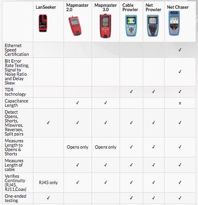
The first place where you’ll have to figure out which cable is which is when you’re retrieving spare premade cables from your extras box. You should only save known good cables, but you can use a basic cable tester with remote to check out continuity and wiring. The Platinum Tools Lanseeker does an excellent job at this.
Common Cable Arrangements — TIA-568A/B
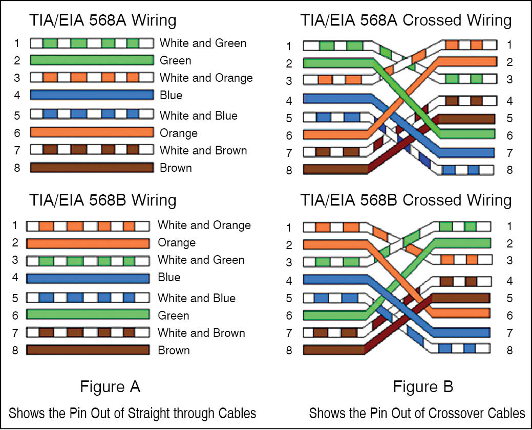
Look at the RJ45 connector on a cable, holding the flat underside toward you. On the left is pin 1. For Ethernet use, the straight through configuration is what you’re likely to see, in TIA-568B arrangement:
- Orange stripe
- Green stripe
- Blue stripe
- Brown stripe
For the less common TIA-568A arrangement, pins one and two are Green stripe and Green, and 3 and 6 are Orange stripe and Orange. The connections are the same, but the colors are swapped. You can identify them that way, and suspect which one you have just by the pin 1 color.
Standard, Crossover, and Rollover
Computer equipment sends data using pins 1 and 2, and receives using 3 and 6. This is part of a convention which is used when these connectors and cables are used for Ethernet. For shorthand, you can call this MDI, or the Medium-Dependent Interface.
In the past, computer-to-computer “crossover” cables were needed when bypassing network equipment. As a variation, they were called MDI-X, for Medium-Dependent Interface Crossover. Network interfaces have advanced enough to detect cabling and switch pin usage as needed, so crossover cables are rarely used.
Crossovers not only exchange pins 1 and 3, 2 and 6 to exchange data and transmit, but also 4 and 5 cross and connect to 7 and 8, exchanging blue and brown pairs. Testers such as the Platinum Tools VDV MapMaster 3.0 can check all of the exchanges in a crossover cable quickly and simply, and identify common wiring problems in the cable such as miswires and split pairs. Of course, it can’t detect wrong wire colors!
For completeness, the rollover cable reverses every pin: 1 to 8, 2 to 7, etc., as if the wires were part of a ribbon cable which was reversed. If you have Cisco networking equipment nearby, you may have a few console cables in your cable box which are wired this way — beware!
Verification and Testing
Testing devices such as the Platinum Tools VDV MapMaster 3.0 can verify cable wiring, check for shorts and opens, and verify more exotic cable configurations such as mixed data and video. They can also map cabling using the remote module.
Testing longer lengths of cable may involve locating shorts and opens, conducting operational tests on data and PoE current transmitted on the wires, and even measuring cable length electronically. The Platinum Tools Cable Prowler can do all that, and much more. By comparing termination wire colors to standard usage and using testing devices, you can identify most cables and put them to use with confidence.
Recent News
Platinum tools announces: digital tone and probe kit, integrated systems europe daily giveaway: ezex-rj45 ®️ mini termination & test kit, cedia expo 2019 daily giveaway: ezex-rj45®️ termination & test kit, infocomm 2019 daily giveaway: ezex-rj45®️ termination & test kit, platinum tools leads tools & testers category in 2018 cepro brand analysis, speeding up network installations, real world certifier rwc1000k vs net chaser, cedia expo 2018 daily giveaway: ezex-rj45® termination and test kits, can a cat6 connector work on a cat5e cable, infocomm 2018 daily giveaway: ezex-rj45® termination and test kits, how to test poe for ip security cameras, ethernet speed certification & network testing, the first bendable rj45 connector, nab show 2018 daily giveaway: ezex-rj45® termination and test kits, isc west 2018 daily giveaway: ezex-rj45® termination and test kits, xpress jack keystone termination kit now available, wire rope cutter now available, keystone cat6a jack, tool-less, now available: ezex-rj45 shielded connectors, best designed j-hook for modern cable installs, the one-handed self-adjusting wire strippers: minim® & maxim®, introducing the net chaser™ deluxe test kit, how to terminate large cat6 or cat6a cabling with ezex-rj45 connectors, how to: install ethernet wall plate with xpress jack™ punchdown tool, new ezex-rj45® termination kits available, platinum tools launches vdv mapmaster™ 3.0 cable tester, infocomm 2017 giveaway: three exo™ ezex-rj45® termination & test kits, winners from giveaway: three exo™ ezex-rj45® termination & test kits during 2017 isc west, giveaway: three exo™ ezex-rj45® termination & test kits during 2017 isc west & nab, register for free: isc west & nab show as a guest of platinum tools, how to avoid installing bad ethernet cable, top 5 reasons you need a cable & network tester, the flex connector: specs met, wiring problems solved, how to terminate cat6a connectors in the field, net chaser™ vs cableiq, the best keystone jack termination technique to prepare for reliable gigabit, net chaser vs cable certifiers, how to avoid disconnection with an ethernet cable lock, how to deliver professional cable and network testing documentation, can my network cable handle 1gb speed, net prowler – identify, monitor & test lan issues, upcoming events, isc west 2024.
Venetian Expo Las Vegas, NV Booth #3036
Click HERE for a FREE PASS
04/10/2024 - 04/12/2024
NATIA Conference
Providence , RI Booth #928
07/14/2024 - 07/18/2024
Cut Strip Terminate Test
- News / Events
- Warranty Registration
- Rep & Distributor Login

Where to Buy
Subscribe to updates, please complete form.
Copyright © 2024 Platinum Tools®. All rights reserved.
Your browser is out-of-date!
Update your browser to view this website correctly. Update my browser now
Home › The Wire
How To Identify, Verify, and Test an RJ45 Pinout
By From The Wire@SVConline
Ethernet cables, the 8-pin variety which are terminated by an RJ45-style connector, can come in just enough varieties to spread confusion. There are four basic types: Rollover type which only looks like an Ethernet cable, but can be useful with Cisco equipment consoles. Usually light blue, sometimes with a 9-pin RS-232 connector on one end. […]
Ethernet cables, the 8-pin variety which are terminated by an RJ45-style connector, can come in just enough varieties to spread confusion. There are four basic types:
- Rollover type which only looks like an Ethernet cable, but can be useful with Cisco equipment consoles. Usually light blue, sometimes with a 9-pin RS-232 connector on one end.
- Straight through type, connecting to networking equipment such as routers, hubs, and switches, which is the predominant cable type now.
- Crossover type which was necessary to connect computer to computer without any intervening network equipment. Becoming unnecessary.
- A fourth type, which has to be mentioned — home made cables with nonstandard pinouts, often non-Ethernet. Hopefully, someone labeled them and identified their use.
Sorting Spares
The first place where you’ll have to figure out which cable is which is when you’re retrieving spare premade cables from your extras box. You should only save known good cables, but you can use a basic cable tester with remote to check out continuity and wiring. The Platinum Tools Lanseeker does an excellent job at this.
Common Cable Arrangements — TIA-568A/B
Look at the RJ45 connector on a cable, holding the flat underside toward you. On the left is pin 1. For Ethernet use, the straight through configuration is what you’re likely to see, in TIA-568B arrangement:
- Orange stripe
- Green stripe
- Blue stripe
- Brown stripe
For the less common TIA-568A arrangement, pins one and two are Green stripe and Green, and 3 and 6 are Orange stripe and Orange. The connections are the same, but the colors are swapped. You can identify them that way, and suspect which one you have just by the pin 1 color.
Standard, Crossover, and Rollover
Computer equipment sends data using pins 1 and 2, and receives using 3 and 6. This is part of a convention which is used when these connectors and cables are used for Ethernet. For shorthand, you can call this MDI, or the Medium-Dependent Interface.
In the past, computer-to-computer “crossover” cables were needed when bypassing network equipment. As a variation, they were called MDI-X, for Medium-Dependent Interface Crossover. Network interfaces have advanced enough to detect cabling and switch pin usage as needed, so crossover cables are rarely used.
Crossovers not only exchange pins 1 and 3, 2 and 6 to exchange data and transmit, but also 4 and 5 cross and connect to 7 and 8, exchanging blue and brown pairs. Testers such as the Platinum Tools VDV MapMaster 3.0 can check all of the exchanges in a crossover cable quickly and simply, and identify common wiring problems in the cable such as miswires and split pairs. Of course, it can’t detect wrong wire colors!
For completeness, the rollover cable reverses every pin: 1 to 8, 2 to 7, etc., as if the wires were part of a ribbon cable which was reversed. If you have Cisco networking equipment nearby, you may have a few console cables in your cable box which are wired this way — beware!
Verification and Testing

Testing devices such as the Platinum Tools VDV MapMaster 3.0 can verify cable wiring, check for shorts and opens, and verify more exotic cable configurations such as mixed data and video. They can also map cabling using the remote module.
Testing longer lengths of cable may involve locating shorts and opens, conducting operational tests on data and PoE current transmitted on the wires, and even measuring cable length electronically. The Platinum Tools Cable Prowler can do all that, and much more. By comparing termination wire colors to standard usage and using testing devices, you can identify most cables and put them to use with confidence.
From The Wire@SVConline
For more stories like this, and to keep up to date with all our market leading news, features and analysis, sign up to our newsletter here .
Featured Articles

Shure Introduces Microflex Advance MXA901 Conferencing Ceiling Array Microphone Alongside Preview of Designer 6.0 Configuration Software

Extron issues supply chain statement

NAB 2024: PHABRIX prepares comprehensive test & measurement showcase
Thatcham, UK – 5 March 2024: Test & measurement innovator, PHABRIX, has announced plans to exhibit its full suite of instruments at NAB 2024, including the Qx, Rx and...
Tools of the Trade Pt. 2
This installment of Tools is mostly about test equipment, but first a few other invaluable hand tools. Over decades many types of terminations that don’t require soldering have come...

Audio-Technica U.S. announces new System Solutions Test Lab
— Located at A-T’s U.S. headquarters in Stow, Ohio, this new facility is used for analysis, testing and demonstration of Audio-Technica’s commercial products with consultants, integrators, end users and...
Inter BEE 2023: PHABRIX to show class-leading test and measurement solutions
Thatcham, UK – 24 October 2023: Test & measurement innovator, PHABRIX, has announced that it is to showcase an extensive selection of its most popular compact and handheld Test and Measurement...

Tools of the Trade Pt. 1
Not a very original title, but tools are necessary to build AV systems. And the right tools make the job go smoother and faster—not to mention maintaining quality. This...
From The Wire

Sennheiser Offers Personal Interactions with its Business Communications Products and Experts During the Connect and Collaborate Roadshow
Published: April 9, 2024
Russound Announces New Generation of Multichannel Amplifiers
Royal Caribbean International Installs Listen Technologies’ Audio Over Wi-Fi Assistive Listening System on new Icon of the Seas
Riedel Powers Unique Live Music Implementation for Ongoing Coldplay Tour
Jeff 1 Comment
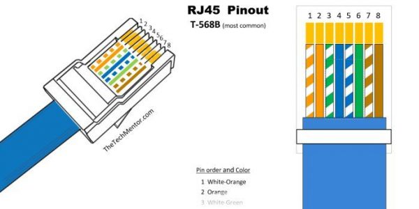
Easy RJ45 Wiring (with RJ45 pinout diagram, steps and video)
Rj45 pinout diagrams, the tools you need and more.
Making RJ45 wiring easy when you have the right RJ45 pinout diagram . Several variations are shown below. I carry Ethernet cable with me all the time so you know it will be useful. To help you memorize it , I created an easy poem so you will always remember the most popular cable wiring color order. I also share a video to help. Just follow the steps below to create your own. If you are looking for an Ethernet crossover cable you can make one following the steps below and paying attention to the relevant note. Read on!
The first thing you need to do when making Ethernet cable is make sure you have the right tools. While I’ll cover that further below, you can also check out TheTechMentor.com article that reviews complete network installation tool kits here .
Stop Press! I found a short-term discount for Cat8 cable. These cables are 30% off! This week only.
I’ll get straight into showing the diagrams and provide more options and details further below.
Make sure you use the correct RJ45 Pinout wiring diagram for your needs.
There are a couple of standards and there is also crossover cable, so make sure you study the RJ45 Pinout diagrams below to get the right one for your needs. The following is for T568 B (most common).
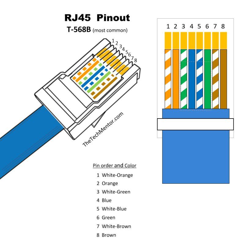
This RJ 45 pin diagram (T-568B) shows everything you need in one handy image, with iso-view and RJ45 color order, suitable for printing quite large.
I like this pinout diagram because it shows everything you need. It includes an isometric view and pin-color order table, all in one large diagram. You can print it for the wall, though the smaller one below also shows what you need within a smaller diagram which may be better to print and carry with you.
You may already know each Ethernet cable has four wire pairs .
All your Ethernet connectors (8P8C) have eight pin slots .
Always face the clip away from you so you see just the flat side with the pins. You count (or label) the cables from left to right from 1 to 8 (easy!).
There are two standards for wiring Ethernet cables, these are T568A and T568B. T568B is the most common and is what we’ll be using for our straight Ethernet cable.
STOP PRESS! – Black Friday Special
If you are in IT (and reading this page, there is a good chance you are!) then you might be interested in something I am getting into at the moment.
It is called Atera, and it would be great for anyone with a small IT services business.
I love the way they charge only for the number of IT professionals using it, so if you are a one-man band or small team (like many of our readers), this might be best option to compete with the big-boys! Of course they are for large business too.
I’m pretty happy because I found they have a Black Friday special at the moment. Sign up for a free test license and you benefit later on if you decide to become a paying customer . There is only upside! Just for your consideration.
If you’re interested or want to learn more, CLICK HERE!
RJ45 Pinout Diagram
As I explained, the most popular and most common is the T568B standard which has surpassed the first standard (T568A). Either configurations wire the pins straight through (i.e. pins 1 through 8 on one end are connected to pins 1 through 8 on the other end, provided you wire them the same at each end ).
Please do also check out the RJ45 Pinout Poem below which is easy to memorize with the aid of the diagram provided and it means you won’t ever forget it!
If you agree the poem might work for you or others, please share it with your colleagues !
Note: as stated above, the tab is away from you (hidden behind) as you count the pins 1 to 8.
Here is a simple RJ45 Pinout Diagram (which still shows the wiring you need):
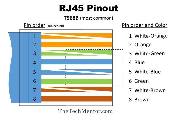
RJ45 Pinout wiring diagram (std T568B). Feel free to print it and carry it with you. If you want a larger diagram see further below. Normally a string of colors is difficult to remember similarly to phone numbers. It is surprisingly easy to memorize these colors as you’ll see. Read on to learn how!
You can follow the step by step instructions further below to make them up.
It might not be practical to always carry this RJ45 pinout diagram with you.
It can be easy to memorize the order, if you know how. I strongly recommend it. Then you can impress everyone that you have memorized it and say the colors in order quickly.
While the RJ45 B pinout wiring order is more recent and more commonly used these days, the T568 RJ45 A wiring order is still quite common (you just want to be consistent and use the crossover cable further below where necessary).
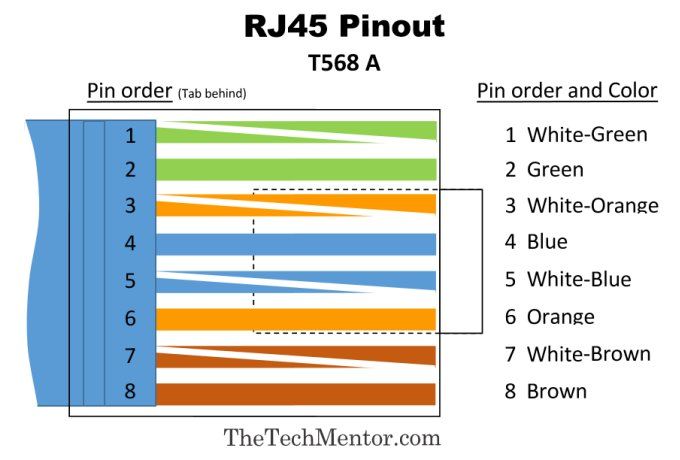
This diagram shows the original T-568 pinout wiring order. Again, as per it’s counterpart shown further above, this one is small but ideal to print and carry with you.
The next pinout diagram below is the counterpart for the more detailed isometric and T-568-B RJ-45 wiring above, showing rj45 pin numbers and color order for T-568 A. Can you pick which pairs are swapped relative to the T-568B wiring diagram?
T568A Wiring Diagram with RJ45 Pin numbers and wiring order:
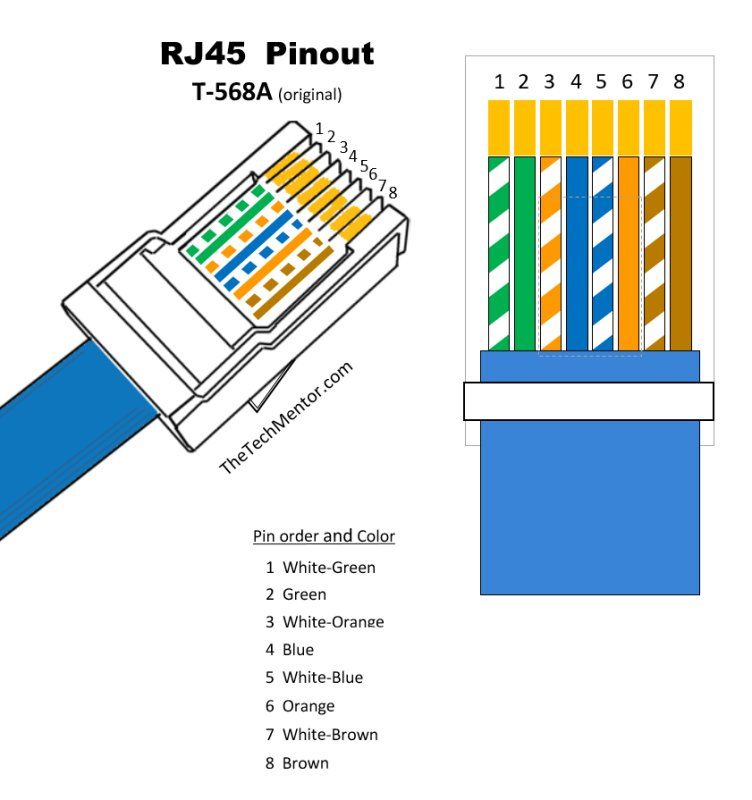
In this RJ-45 A wiring diagram you can see the isometric view and color order. The swapped wiring order pairs are explained further below.
I mentioned a way to memorize the RJ45 Pinouts. The way to do it so you never need to rely on printouts again is by using the memorization tools below.
RJ45 Pinout Poem
First a question; what thing has color that also is has the name of the color? An orange of course!
This is the first wire pair base color.
This poem (or riddle) yields the colors of wiring to pin 1 through 8. See further below as to how this mnemonic (memorization technique) helps you remember the RJ45 pinout order.
Remember you saw it here first on TheTechMentor.com!

The RJ-45 Pinout diagram poem and picture is for the more common T568B RJ45 wiring.
While an Orange is Orange
What Green eyes are Blue?
When Blueberries in Greenland
Want Browner Brownies too!
It works well as the construction of the poem is made to match the RJ45 pinout. The riddle, with the wire colors used, only makes sense in this order.
Memorization Techniques included:
There are several patterns, rhyming verses and emotional elements to note which really help you remember it.
- The orange is first on top and easiest of all to remember since an orange is orange ! So it goes first.
- Each pair has a ‘w’ letter first combined with the following letter, thus giving the white striped wire color first of every two wires. This is a helpful pattern to remember.
- The question and answer format (2 lines each) or riddle helps keep the pattern straight.
- You’re asking what green eyes are ‘ blue’ (sad). There are so many songs talking about certain color eyes being blue (sad). In this case we ask what green eyes are blue. It probably should be ‘whose’, but to make a sound closer to ‘white’ we ask ‘what’ instead.
- The answer relates to blueberries of Greenland. Remember a country that has a color – Ireland just wouldn’t work here! The sad little blueberries have to be on something – they are on the land, so they come first before the land (blue before green).
- In the end, the brownies followed by ‘too’ give a rhyme with ‘blue’. The critters want darker brown brownies like everyone else has. The last two main colors are the same (brown and brown) just as the first two main colors are the same (orange and orange).
It helps that you remember the image too, as each wire pair color is in order top to bottom (and left to right).
I recommend you draw it out, in color (optional). I suggest you do this and repeat the poem while you do it.
If you do, you will always remember the RJ45 pinout and you will not need a diagram anymore!
It’s a silly image and that also helps you remember it .
How does the poem provide the colors?
So the poem with the color codes explained is like this.
While an Orange is Orange (W-O, O)
What Green eyes are Blue? (W-G, B)
When Blueberries in Greenland (W-B, G)
Want Browner Brownies too! (W-B, B)
I’ve put a larger version below as well in case you want to take a copy.
NOTE: you are welcome to print so long as you keep TheTechMentor.com on the printed image, and if you have a website you are welcome to use on a website so long as you link back to this article. Use of the poem also requires a link back to this article (thank you).

RJ45 Pinout poem picture explanation, giving WO, O, WG, B, WB, G, WB, B for the wiring to pins 1 to 8 (for T568B RJ45 wiring). [You are welcome to print so long as you keep TheTechMentor.com on the printed image, and use on a website so long as you link back to this article.]
Note: if you mumble the RJ45 Pinout Poem, it sounds like you are saying the pinout order!
Tell me what you think!
Please comment below and let me know what you think. Do you like my new Pinout Poem and think it will help you or someone you know? Is it bad? How could it be better?
Do you like my artwork (the RJ45 Pinout Poem Pic.)?
Should I not give up my day job just yet?
Okay, so you may not be interested in the poem. If not, then the tables below provide you with a serious view of the data.
Ethernet Cable Plug RJ45 Pinout (Wiring Color) Table for T568B
The table below show the proper Ethernet plug wiring with orientation of the colored wires to the pins for the Cat6 Cable we’ll make (ie. the more common T568B standard cable, with a spine). See also the diagrams further below within the step by step instructions.
Ethernet RJ45 Pinout for T568A
Just for completeness I’ll list out the cable color order for the other Ethernet cable plug standard (T568A). Remember not to mix the two on one cable! Unless you want a crossover cable.
Ethernet RJ45 Crossover Cable Wiring
NOTE: Of course if you want to make a cross over cable, then you can make the cable wiring to the different standard alignments at each plug (i.e. one end will have the T568B and the other the T568A). There is also a diagram of this showing the wires in color further below.
Ethernet Crossover Cable Wiring Pinout
In RJ45 Ethernet crossover cable wiring, it is almost as easy as 1, 2, 3 . They are the first three numbers to remember anyway.
Yes, here come some more memorization techniques!
You can remember which cables are switched by remembering twelve thirty-six to thirty-six twelve ( 12 36 to 36 12 ) for the Ethernet cable plug pin numbering above.
That means 1 goes to 3, 2 goes to 6; 3 goes to 1 and 6 goes to 2.
This gives you the relevant switch of T568A to T568B (and vice versa, i.e. T568 B to T568 A).
- It is easier to remember because it makes it seem like just 2 pairs of numbers, then reversed.
- First pair is 12, say like 12 months in the year.
- Second pair is 36, (well, 3 follows on from 1 and 2, and 36 is three times 12 the first pair).
- Or using 1, 2, 3: the first numbers are 1, 2 and 3, and the last number is 1 x 2 x 3 which equals 6.
It helps if you can remember that the first three numbers are 123. So easy! 3 is the hook to get the final pair, as 12 times 3 gives the second pair. There are many different memorization hooks you can use.
Still having a little difficulty visualizing the crossover pinout? Here is a diagram I hope will help.
RJ45 Crossover Cable Pinout
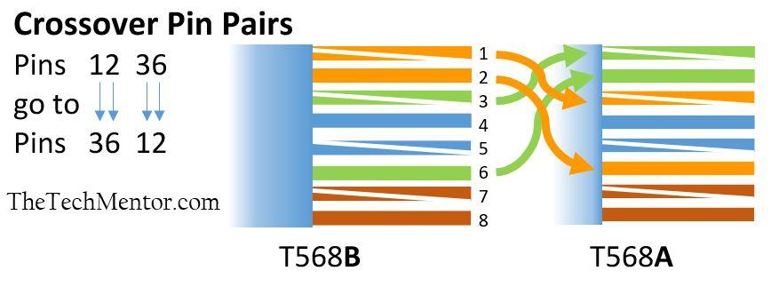
RJ45 Pinout to make an Ethernet crossover cable. This is useful to visualize the ’12’ ’36’ to ’36’ ’12’ pinout rj45 crossover pattern, making it look simpler than it sounds. Note all we really have is the orange base color pair swapping with the green base color pair.
Okay, now on with the method.
How to make an RJ45 Ethernet Patch Cable Like a Pro!
Follow the step by step instructions below.
Note: The term ‘patch’ cable is just another way to describe a shorter or room-run cable.
Step 1: Cut and Strip
The cable not you! (Wink!)
Cut and strip the cable jacket about one and a half inches to the end. As we state elsewhere we own the TRENDNet cut and strip tool, but obviously use the one of your own preference. See further below for the tool links.
Step 2: Spread the Ethernet Cable Wires
Spread the four wires apart. For Cat 5e, you can use the pull string to strip the jacket farther down if you need to, then cut the pull string. As you may know, you need to cut out the spine from a Cat 6 cables before inserting into the Ethernet cable plug.
Step 3: Untwist the Wire Pairs
Untwist the wire pairs and neatly align them in your chosen orientation based on the RJ45 pinout, my pinout poem, the table(s) above or the RJ45 Ethernet pinout image below (T568B shown).
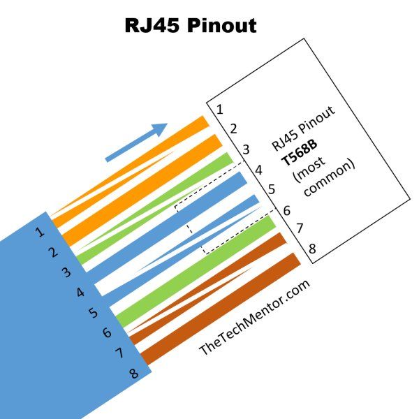
Basic RJ45 Pinout wiring diagram T568B as you insert into the RJ45 Connector (note tab is at the back)
This is a simpler version. Otherwise you can use the more detailed RJ45 Pinout Diagram 1 above.
NOTE: Do not untwist them down the cable further than where the jacket begins; you should aim to leave as much of the cable twisted as possible.
Step 4: Cut Again (Evenly)
Cut the wires as straight as possible, about half an inch from the end of the jacket. This is important as you want them all to sit evenly inside the cable plug. If you want to, you can hold it against the boot and mark with a permanent ink pen first.
Step 5: Insert Wires Into the Ethernet Cable Plug
Carefully insert the wires all the way into the modular connector, making sure that each wire passes through the appropriate guides inside the connector. Again, make sure you reference the RJ45 pinout diagram at this crucial step until you have it memorized.
Step 6: Crimp It!
Push the connector inside the crimping tool and squeeze the crimper all the way down.
So that is one end of our RJ45 wiring.
Repeat the above steps to attach another plug to the other end of the cable.
As I wrote above, you can make an Ethernet crossover cable by making the other end as a T568A, as per the image below.
RJ45 Pinout Diagram for T568 A
The RJ45 Ethernet Pinout below is still used, it’s just that the T568B is more common these days. It effects how the wires spread out from the main cable. In the end though, so long as you make sure you use the same pinout at each end, you will have your working Ethernet cable.
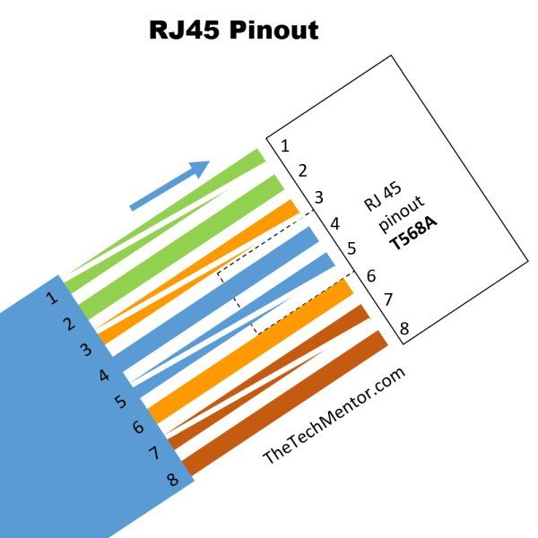
Cat5 Pinout diagram showing how to make an Ethernet plug wiring as inserted into the RJ45 connector
Ideally, to make sure you’ve properly terminated each end of the cable, use a cable tester to test each pin (see the link to a cheap cable tester in the tools below). This is when you will know if you cut your wire pairs evenly enough!
To make an Ethernet Crossover cable, your cable pugs would be terminated like so:
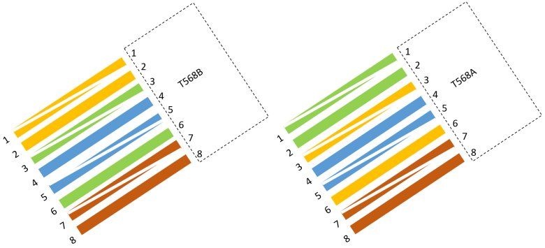
Ethernet crossover cable end boots. Can you see the 12 36 to 36 12 pattern? Tabs are to the back (as usual).
Now that you’ve made your cable, then what? You might like to use it as Ethernet cable for gaming in your own LAN or maybe to connect up to the internet. It is a nice feeling to stop and remind yourself that you are using the Ethernet cable you made !
If you are looking for Cheap RJ45 cable plugs (Ethernet cable connectors) and Ethernet wiring etc., please see the links below.
If you are going to do a Network Tech Course (The Cisco CCNA for example) get yourself a head start by following this guide to get some practice in.
Before you can get started, you need to make sure you have the necessary tools, and decide whether you’re going to use Cat 5e or Cat 6 network cables (the ones with the spline to increase separation distance for performance reasons).
I hope the list below helps.
Legal Note: These links are provided for your benefit and are not necessarily recommendations by us of one brand over another. A helpful list is what we want to provide – if you have suggestions for others, please put it in the comments at the end of the article. We might get a very small fee for referring you, provided your purchase qualifies, that won’t affect your cost.
25ft CAT6 Patch Cable
You are going to make one of these, but you can start off with a long CAT6 cable and make several smaller ones for practice following the RJ-45 Pinout diagrams above. They will come in handy later too. I always carry a patch cable in my toolkit for obvious reasons, so it is a good idea to get a long one anyway.
The longer the better especially when trying to plug in to a wall port or switch that fortune has it way of in the distance. Or you can cut and practice more wiring and crimping.
If you want you can just get a cheap ‘Amazon Basics’ cable:
You can find their Unshielded twisted pair (UTP) patch cable here> .

Pink rj45 crossover cables are all the rage.
PINK is the New Black! Er.. Blue?
You might know you can get these crossover cables in different colors now.
You might love the 10 ft pink patch cable here !
Or you might like to find your own cable color for that matter. Maybe it’ll become the trademark of your installations!
Shout out to our women in tech!
Do NOT forget PURPLE! Follow the link and search for that if you like!
Okay, so those are some short cable options. Feel free to search around and find your own source. Moving on!
Buy Cable in Bulk = Cheap RJ45 Cable!
You might be ready to buy in bulk to save. To do this you want to look for pull cable like the following.

1,000 ft bulk Cat5e Ethernet Cable (Wire UTP with Pull Box Cat-5e-Style Grey Cable)

Cat5e Ethernet cable
This bulk cable of 1000 ft (308 meters) is by far the cheaper way to buy it. But it might just be too big and too much so I list it last. If you are just starting out I think you could get it as there will always be applications and it will go quicker than you think.
If you look closely at the picture, you can see there is the center hole in the wall of the box, so you can pull through as needed (great for long runs) with the clip to hold the end of the cable until next use.
Cat 5 RJ45 connectors
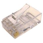
Get a big pack of Cat 5 connectors
RJ45 Connectors
Used with my TRENDnet Crimp Tool to make new cables or repair damaged ones. Buy a big pack! You will probably use many of these.
(These connectors are also called 8P8C plugs.)
RJ45 Female to Female Straight Coupler
I carry one of these around with me just in case I need to quickly make a longer cable. This one is optional for this exercise, but handy if you cut your long cable and then need to reconnect it!
These do not look the best in my opinion, so you might prefer couplers like these . Depending on what you’re going to be doing, you might also consider to buy the following tool now, although it is optional for now (did I say it is optional?).
Fluke Network Pro3000 Toner and Probe Kit
I use the Pro3000 for toning and tracing out Ethernet wires. It’s especially handy when the cable installers don’t label any of the ports! If you are going to be installing cables – THEN LABEL THE PORTS please!
And you will probably want other cables in time.
Additional Cables you might consider while you are at it:
- Firewire 800 to Firewire 800
- Firewire 400 to Firewire 800
- USB A to Type B
- USB A to Mini B
- and USB A to Micro B
Tools to Connect Your RJ45 Wiring
I mentioned above that there is another article with all the tools to help you make your RJ45 wiring, but I’ll put a few of the most relevant ones below too.
What you’ll need to use when following the above RJ45 pinout pics.
TRENDnet RJ11/RJ45 Crimp/Cut/Strip Tool
I use these for not only making new network cables but also replacing damaged RJ45 connectors on existing cables, using the RJ45 pinout poem shown above of course!
This is my preferred brand of Crimp and Strip tool. If you want you can search around on Amazon to find a brand to your liking (or price for that matter!).
Klein Tools Ratcheting Crimper

Brilliant for cutting stripping and crimping.
Ratcheting action makes it easier. Versatile as it crimps 4, 6, and 8 position modular connectors (RJ22, RJ11/RJ12, and RJ45).
Network Cable Tester
This basic network cable tester is used to determine if your cable is good, bad, or wired incorrectly. You will always use this one or one like this.
Also for a bigger list, I have written an article that gives you all the consumables along with a list of tools you’ll need as a computer repair technician (don’t worry if you never want to become a computer repair tech, but this list is gold!).
It has pretty much all the consumables you will need as well as the tools I use and have found to be the best in my work.
If that’s not enough of an explanation of how to make your own Ethernet cable, here is a video!
Here’s simple video tutorial that takes less than 10 minutes that shows anyone can do it. Do check out my links just above to check pricing before you buy any tools!
Are you new to Making Cables and Installing Networks?
If you are looking for RJ45 Pinouts then likely so! You would be well advised to check out Mike Meyers book on the CompTIA network plus book below. We have mentioned Mike Meyers books before, but of course you could check out a few books and get a different CompTIA network plus book if you prefer.
It’s very handy and as typical the CompTIA study course covers a lot of the basic knowledge or foundational knowledge that you need.
I know you may not intend to do exams and become a certified computer network technician. However, this book does provide worthwhile knowledge before you start cutting and crimping to any large degree.
For beginners, it is a book covering the basics and really is an essential network technician’s tool regardless of whether or not you intend to actually sit the CompTIA test.

Mike Meyers’ CompTIA Network+ book is a great way to leapfrog your computer networking knowledge. Click the cover image to check it out on Amazon.
Well that wraps up this article all about RJ45 Pinout diagrams and wiring steps. I really hope you find the memorization techniques helpful so you can memorize the wiring colors. After all, that is why I created it! Please add your comments below.
Summary of how to make RJ45 Wiring Easily
I’ve shown step by step instructions how you connect each RJ45 Ethernet cable plug in order to make up your Ethernet patch cable (or RJ45 crossover cable) with a bonus video. You now have TheTechMentor.com’s RJ45 Pinout Poem, and the silly memorable image so that you might never need a pinout diagram again! Plus you now have all the RJ45 Pinout diagrams you will need to follow.
Related posts:
- How to Make an Ethernet Patch Cable
- Powerful memorization techniques that boost performance
- DPC Watchdog Violation Fix Steps
- Clarify and select Cat5 vs Cat6 Ethernet cables
- Tips to Get a Faster Internet Connection
About The Author
Jeff (Surname withheld for family privacy) is an engineer with over 26 years experience. He first learned to program in Fortran 77 ! See the 'About Us' for more.
I second the Female to Female couplers. Keeping half a dozen or so in my glove box was a life saver back when I was doing field work. The toner and probe kit is also seriously useful to have for a number of tasks but if the cost is off-putting you can get away using a cable tester to identify unlabelled (or incorrectly labelled) ports.
Leave A Response Cancel reply
* Denotes Required Field
GAMING ?!: Have you thought of…
Recent posts.
- Creative Business Marketing Strategies That Can Benefit You
- How Technology Reshapes Secretary Services: A Digital Evolution
- Harnessing Innovation: Technology’s Power in Enhancing Freight Brokering
- Keep Your Digital World Running Smoothly With These Inside Tips
- Breaking Down Digital Marketing: A Beginner’s Guide
Computer Tech Popular Posts
- Accessories
- Apple/Mac/OSX
- Certifications
- Customization
- Data Recovery
- Flash Drive
- IT Business startup
- Surface Pro
- Uncategorized
- Web Hosting
Can’t find it in Categories? – Use Search:

Latest Comments
- Alan on How to Remote Control Computers Using PCHelpWare
- Anna on Clean iPhone cable or port to fix intermittent charging
- Jeff on The Best Computer Network Installation Tool Kits
- Kevin on The Best Computer Network Installation Tool Kits
- Ibrahim ibrahim Fagge on Free Computer Repair Flowcharts
Copyright © 2006 - 2024 · TheTechMentor.com · All Rights Reserved
- Terms Of Service
- Privacy Policy
- FTC Disclosure
Ethernet RJ45 Cable Tester

Introduction: Ethernet RJ45 Cable Tester

this is my first instructable, so forgive my less-than-optimal description (and some missing photos)-
The idea (well, the need, actually) was to check the proper cabling of a long (40m or so) ethernet cable from my flat to the basement; the routing itself was tricky, with a lot of narrow passages, so the probability of damaging the cable was high. Obviously I had no professional ethernet tester available!
I got inspiration from xklathos' DIY-UltraCheap-RJ-45-UTP-Cable-Tester project, but it had a big limitation, in my case: it is not applicable when the two ends of the cable under test are far away, i.e. with the cable already in place.
Furthermore, I wanted something that was able to detect short-circuits, errors in wiring at the connectors, and, as an addition, suitable both for straight-through and cross-over cables.
There are plenty of "smart" projects out there, all relying on integrated circuits and leds, to perform a cyclic test of each channel, but I had no such hw available.
Summarising, the required characteristics are:
- capable of testing cables "in-place"
- open channels,
- short circuits,
- wrong wiring
- applicable to Cat 5, 5e, 6 cables, shielded and unshielded
- minimum hw required
The project ended in a "passive-only" couple of terminals, to be used in conjunction with a multimeter capable of reading resistances-
So... let's go!
Step 1: Collecting What Is Needed

- 3x female RJ45 shielded connectors ("jacks") (for example from a broken/old router/switch); you can use also unshielded jacks, but of course you cannot test STP cables for shield continuity
- 2x small breadboards
- 8x 1kOhm resistors "RA" (or similar value, the important is that they are equal to each other, and at least 2 orders of magnitude higher than the cable resistance...anything in the range of 470-4700 Ohm should be OK)
- 1x 10kOhm resistor "RB" (or similar value, proportional to the 8 above)
- about 20 cm of ethernet cable
- some shrink tube (small diameter)
- knife/cutter/scissors
- solder and soldering iron
- multimeter, measuring resistances
- hot glue gun (optional, even silicon sealant, vinyl glue, foam, anything to avoid shorting wires..)
Step 2: Preparing the Sockets

if you have 3 new female jacks of the wall-mounted type, for each of the jacks:
- prepare a 6 cm piece of the ethernet cable, removing external insulation cover
- separate each wire
- insert the individual wires in the slots of the jack, press them with the tool or its cover
- use another wire to connect the shield
- remove individual insulations at the other end of the wires
if you have an old router/switch/NIC:
- cut the PCB around the jacks, until you have 3 single connectors, already soldered in their small piece of PCB
- with a file or sand paper, smooth any edge of the PCB
- prepare a 4 cm piece of the ethernet cable,
- remove external insulation cover
- completely remove individual insulation
- solder each of them on the protruding ends of the leads
- use another piece of naked wire to connect the shield
Step 3: Remote Terminal

This unit will be passive only, with only one female RJ45 connector on it, and all the resistors:
- cut a piece of breadboard a bit larger than the jack (let's say 10 holes), and twice longer (let's say 15 holes)
- take one of the already prepared sockets
- insert the wires from the jack into a strip of 8+1 holes, and solder them (if you used salvage connectors, insert the naked wires in as much as possible, in order to avoid short-circuit between them)
- trim the exceeding length of the wires
- use hot glue to fix jack and breadboard to each other, thus avoiding short circuits
- insert and solder the resistors according to the schematic
Step 4: Local Terminal

This unit will be the measuring one, with two RJ45 connectors (for testing both straight-through and cross-over cables, otherwise you can use only the straight-through connector):
- cut a piece of breadboard a bit larger than two jacks width (let's say 13-14 holes), and 14-15 holes long
- take the two already prepared jacks
- insert the wires from the jacks into a matrix of 4x2 holes (plus 1 for shield), and solder them (if you used salvage connectors, insert the naked wires in as much as possible, in order to avoid short-circuit between them)
- trim the exceeding lengtt of the wires
- use hot glue to fix jacks and breadboard to each other, thus avoiding short circuits
- use short pieces of the remaining wires to make point-to-point connections of the connectors terminals, according to the schematic above (pay attention at the swap between pairs 1-2 and 3-6!!); if needed, use shrink tubes to help with insulation
- with the multimeter, verify for absence of short-circuits
- again, use hot glue to fix all the wiring to avoid damage/shorts etc..
- optionally, solder some rods at the test points, to facilitate use
Step 5: Using the Ethernet Tester

Ok.. everything is ready
Now we need a prepared ethernet cable (hopefully working!!!) as a test unit.. let's start with a straight cable.
- plug the connector at the "remote-end" of the cable into the "remote terminal"
- plug the "local-end" connector in the "local terminal" ("straight" receptacle)
- set the multimeter in "Ohm" mode, with the appropriate range (greater than 8xRA, or RB)
- connect the "black" multimeter probe to the Test Point 1 ("TP1" in the schematic), used as common reference
- if the cable is OK, the multimeter will display a value close to RA*n for each single point (for example, with the 1kOhm resistors, you should find 2 kOhm on TP2, 3 kOhm on TP3, and so on)
- if you see (almost ) 0 Ohm, there is a short circuit between wire "1" and the wire under test
- if more than one TP show the same resistance value, this means there is a short somewhere along the cable
- if you see infinite resistance on TP"n", this means that wire "n" is interrupted somewhere
- if you see infinite resistance on all channels, this means that wire "1" is interrupted somewhere
- if the above formula is not matched with the right sequence, this means that there is some improper wiring
- it the shield is OK, you should see the value of RA+RB (11 kOhm, for example)
- if you see inifinite resistancet, shield is interrupted somewhere (unlikely) or is not present at all in the cable (probable)
- if you see a resistance lower than RA+RB, it is short-circuited with another channel
If you have a crossed cable, simply use the "cross-over" receptacle, and the process is the same
NOTE 1: in the pictures you will see different values on the multimeter display, because I had no 1kOhm resistors available for the prototype
NOTE 2: To Be Done: find a small enclosure for the two terminals, to give them a more "solid" appearance
NOTE 3: by the way, the flat-2-basement cabling, tested with this tester, was OK!!
NOTE 4: all the post production was done with Free/Libre Software :
- photo editing: GIMP 2.8 (GNU General Public License v.3)
- schematic drawing: QUCS 0.0.18 (GNU General Public License version 2.0)
- publishing: Firefox 57.0.3 (Mozilla Public License 2.0)
Recommendations

Making Time Contest

Remake It - Autodesk Design & Make - Student Contest

Fix It Contest


Main navigation

LAN Scout ® Jr. 2 Cable Tester
- Cable tester for data (RJ45) terminated cables and patch cords
- Large backlit LCD for low lit areas displays pin to pin wiremap results
- Test for Open, Short, Miswire or Split-Pair faults, Cross-over and Shield
- Intuitive user interface features three buttons with simple, easy-to-identify test responses
- Tone on single wire, wire pair or all 8 conductor wires
- Multiple style tone generator (solid / warble); requires probe Cat. No. VDV500-123 (sold separately)
- Auto Power-Off feature; 10-minutes in test mode, 60-minutes in tone mode
- Soft, slip-resistant, rugged overmold for easy gripping and durability
- Replaceable 2 x AAA batteries (included)
- Replaceable self-storing remote (included)
- Replacement remote available; sold separately (Cat. No. VDV999-200)
The LAN Scout® Jr. 2 Cable Tester tests installed or loose data (CAT 5e, CAT 6/6A) cables terminated with RJ45 connectors. It also, tones cables with multiple tone frequencies. The larger display is backlit for easier reading in low lit areas. This model uses 2 x AAA batteries (included). Three buttons provide an intuitive user interface.
Specifications
Additional information.
- Always wear approved eye protection.
- Read all safety Information before using the product.
- Carefully read all instructions.
- Designed for use on unpowered/dark cable systems.
- Do NOT connect to live AC power.
- For indoor use only.
Replacement Parts
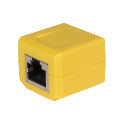
Replacement Remote for LAN Scout ® Jr. 2 Continuity Tester
Accessories.
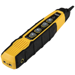
Probe-PRO Tracing Probe
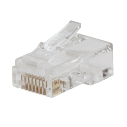
Pass-Thru™ Modular Data Plugs RJ45-CAT6, 10-Pack
Related items.

Twisted Pair Installation Kit with Zipper Pouch

VDV ProTech™ Data Kit
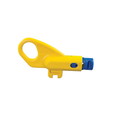
Twisted Pair Radial Stripper
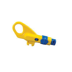
Combination Radial Stripper

Ratcheting Modular Crimper/Stripper
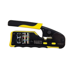
Ratcheting Cable Crimper / Stripper / Cutter, for Pass-Thru™
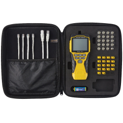
Scout ® Pro 3 Tester with Locator Remote Kit
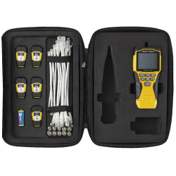
Scout ® Pro 3 Tester with Test + Map™ Remote Kit
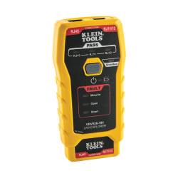
Network Cable Tester, LAN Explorer® Data Cable Tester with Remote
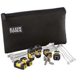
Test + Map™ Remotes (#7 - #12) Expansion Kit for Scout® Pro 3 Tester
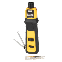
Impact Punchdown Tool, 66/110 Blade
- All Electronics Projects
- Community Projects
- NEW | DIY Webinars
- Submit Your Project
- Mini Projects
- College Projects
- Advanced Projects
- AI/ML Projects
- Reference Designs
- S/W Projects
- Tech Trends
- Tech updates
- Aerospace & Defence
- Communication & Networks
- Energy & Power
- LEDs & Lighting
- Testing Times
- Thought Leaders
- Industry Powered Content
- NEW @ Electronicsforu.com
- New Products
- Innovative Components
- Components Corner
- Tech Updates
- Press Releases
- Electronics Calculators
- NEW | Events
- Premium Content
- Startup Contests
- Design Contests
- Explore Components on DigiKey

RJ45 Cable Tester
RJ45 cable tester circuit
Fig. 2 shows the circuit diagram of RJ45 cable tester. The circuit makes use of easily available components such as timer NE 555 (IC1), decade counter CD4017B (IC2) and a few other components. IC1 is a popular timer, wired in astable multivibrator mode generating output pulses of around 1Hz at pin 3.
Download PCB and component layout PDFs: click here These pulses serve as a clock for decade counter IC2. The outputs O0 through O3 of IC2 go high one after another with the input pulses at pin 14. These are connected to the RJ45 socket CON2 such that a pulse is sent through one leg of each wire-pair and the return legs are connected to ground via LEDs showing the current flow in each pair. Resistors R3 through R6 are used to limit the current through each LED. Output O4 resets the counter IC2 on every fifth clock.
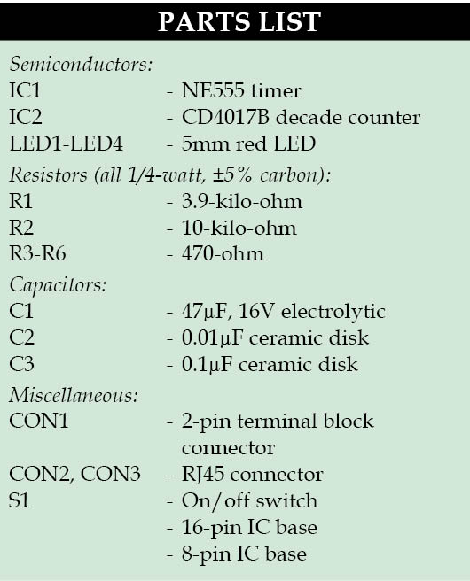
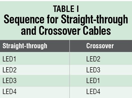
If the LEDs glow in the sequence of LED1, LED2, LED3 and LED4, the cable under test is straight-through type and is working well. Similarly, if LEDs glow in the sequence of LED2, LED3, LED1 and LED4, the cable is crossover type and is working well. Refer Table I for the sequence of LEDs.
Construction and testing
A single side PCB for RJ45 cable tester is shown in Fig. 3 and its component layout in Fig. 4. After assembling the circuit on PCB, enclose it in a suitable plastic case.
Mount all the components on the PCB and enclose it in a plastic cabinet. Make arrangements in the cabinet such that CON1, CON2, CON3, S1 and LED1 through LED4 stick out of the cabinet for proper operation. The circuit is simple and does not require much testing, but do check various voltage levels on test points corresponding to test point table.
The article was originally published in March 2014 and has been recently updated.
- ece projects
- electronics projects
- mini projects
Hi, I have made this tester on strip board using the schematic diagram, and it worked first time. Just to make it on PCB I printed the PDF’s and transferred figure 3 onto the copper plate by ironing it on from a copied image. It didn’t work, I’m thinking that the image is reversed and that at least IC2 is out of sync with R3-6. Can you please confirm if my thinking is correct. I love the circuit, its simple and meets all my needs. Regards, Jim
Hello to all, I came across this little circuit and used a few spares from the projects pile and it works well. Not used the foil patton tho.
Thank you for your feedback.
SHARE YOUR THOUGHTS & COMMENTS Cancel reply
Log in to leave a comment
Unique DIY Projects
Low-cost long range air-tag using indusboard, super power saving 24μa sensor node, smartwatch-based login system using indusboard coin, smartwatch with keyboard and mouse functionalities using indusboard, electronics news, muscle-powered flexure device for biohybrid robotics, qualcomm announces products for iot, edge computing, advancement in selective soldering technology with synchro 3, power analyzers for electrical measurements, truly innovative tech, first smart lidar for the security industry, world’s most advanced 5g modem-rf system, world’s smallest and lowest power uwb soc, analog switches to monitor & protect 1.8 v electronic systems, most popular videos, live diy: how to make a digital thermometer, esp8266 ntp clock with youtube subscriber & views counter display, live diy: dual mode stopwatch, live diy: make your own multipurpose security system, electronics components, wireless soc reference design , paper-based magnesium-air battery for wearables, compact robotics and automation reference design kit, selenium-silicon tandem cells with efficiency upto 40%, calculators, hex to ascii converter, symmetric stripline impedance calculator, broadside coupled trace inductance calculator, lenz’s law and faraday’s law calculator.

Network Consists of Further Focused Websites (Channels)

Inspired by our flagship publication
Electronics for you.

- Sample For Free
- Subscribe For Print
- Subscribe For Ezine
CHECKED OUT EFY EXPRESS?

- READ E-ZINE
© Copyright 2024 - EFY Group © Copyright 2022 - EFY Group

IMAGES
VIDEO
COMMENTS
Common Cable Arrangements — TIA-568A/B. Look at the RJ45 connector on a cable, holding the flat underside toward you. On the left is pin 1. For Ethernet use, the straight through configuration is what you're likely to see, in TIA-568B arrangement: Orange stripe. Orange. Green stripe. Blue. Blue stripe.
Common Cable Arrangements — TIA-568A/B. Look at the RJ45 connector on a cable, holding the flat underside toward you. On the left is pin 1. For Ethernet use, the straight through configuration is what you're likely to see, in TIA-568B arrangement: Orange stripe. Orange. Green stripe. Blue. Blue stripe.
Testing features include: RJ45 BNC Coaxial Master display Remote display Wire mapping Master unit testing only Shield/ground test The LANtest includes two short RJ45 to BNC adapter cables that allow you to test coaxial connections that are terminated on BNC. Also includes one BNC male-male adapter, one RJ11 modular cable, and instruction sheet.
RJ45 pinout diagram shows wiring for standard T568B, T568A and crossover cable! CLICK to check the right one for you or print as reference. See recommended tools. Remember the RJ45 wiring order. THE complete Ethernet pinout cable wiring reference with wiring step-by-step guide. CLICK to find, view, print and more.
THE CIMPLE CO Universal Network Cable Tester Tool - BNC, RJ45, RJ11, USB 4-in-1 Wire Multi-Tester: ... This multi-functional tester tool was made to evaluate and analyze installed wiring or patch cables. Itâ s specifically designed to test four of the most commonly used cables â the RJ-11, RJ-45, BNC and USB. ...
Network Cable Tester RJ45 RJ11 for CAT5/CAT6 Telephone Network Ethernet, LAN Cable Tester for UTP Network Ethernet LAN Multi-Functional Wire Test Tool Equipment. ... Includes Connectors for Cat5e / CAT6 Data Applications, Pack of 50. 4.7 out of 5 stars. 359. 200+ bought in past month. $66.79 $ 66. 79. FREE delivery Fri, Apr 12 . Or fastest ...
prepare a 6 cm piece of the ethernet cable, removing external insulation cover. separate each wire. insert the individual wires in the slots of the jack, press them with the tool or its cover. use another wire to connect the shield. remove individual insulations at the other end of the wires.
An RJ45 tester, a crucial tool for networking professionals, is designed to test the integrity and connectivity of Cat 5, Ethernet, and other network cables. It helps diagnose issues, verify cable installations, and ensure that Ethernet testers are up to industry standards. This versatile tool is indispensable for efficient and reliable network ...
The orange pair is always on the left-hand side of T586B cables. The green pair is on the left-hand side of the less common T586A configuration. Another way of identifying the right RJ45 pinout is to use a network cable tester. When connecting unlike pieces of equipment, always use a straight-through cable.
About This Product. The LAN Scout Jr. 2 Cable Tester tests installed or loose data (CAT 5e, CAT 6/6A) cables terminated with RJ45 connectors. It also, tones cables with multiple tone frequencies. The larger display is backlit for easier reading in low lit areas. This model uses 2 x AAA batteries (included). 3 buttons provide an intuitive user ...
This Pass-Thru Cable Installation Kit includes the tools needed to connect and test Klein Tools' RJ45 Pass-Thru connectors onto category cables. Test CAT3, CAT5e and CAT6/6A cables with the LAN Explorer Data Cable tester. The kit includes the tester, a Pass-Thru crimper, a pack of 50 CAT5e/CAT6 Pass-Thru connectors and a zippered storage pouch.
The LAN Scout® Jr. 2 Cable Tester tests installed or loose data (CAT 5e, CAT 6/6A) cables terminated with RJ45 connectors. It also, tones cables with multiple tone frequencies. The larger display is backlit for easier reading in low lit areas. This model uses 2 x AAA batteries (included). Three buttons provide an intuitive user interface.
RJ45 Pinout. A RJ45 connector is a modular 8 position, 8 pin connector used for terminating Cat5e or Cat6 twisted pair cable. A pinout is a specific arrangement of wires that dictate how the connector is terminated. There are multiple pinouts for RJ45 connectors including straight through (T568A or T568B), crossover, rolled, T1, and loopback.
Fig. 1: Straight-through and crossover network cables. Fig. 2: Circuit diagram of RJ45 cable tester. Fig. 3: A single side PCB for RJ45 cable tester. Fig. 4: Component layout for the PCB. Download PCB and component layout PDFs: click here. These pulses serve as a clock for decade counter IC2. The outputs O0 through O3 of IC2 go high one after ...
Get free shipping on qualified Network Cable Testers products or Buy Online Pick Up in Store today in the Electrical Department. ... The LAN Scout Jr. 2 Cable Tester tests installed or loose data (CAT 5e, CAT 6/6A) cables terminated with RJ45 connectors. It also, tones cables with multiple tone frequencies. The larger display is backlit for ...
★【 CONTINUITY TEST & WIRING DIAGRAM TEST FUNCTION 】 This network cable tester can do the continuity test, which can help you check whether your cable is working normally. ... RJ45 Cable Tester Network Cable Tester Ethernet Wire Test Tool for LAN Phone RJ45 RJ11 RJ12 Cat5 Cat5e Cat6 Cat6a Cat7 UTP/Shield Cable. 4.3 out of 5 stars ...
Please Subscribe =) Road to 100K!- Full Playlist: https://www.youtube.com/playlist?list=PLz1UQhw0O7bZmHen1FJudpHK_MryCq6-JWalkthrough00:00 Intro- CHAPTER 20:...
IL-2 Sturmovik - Update 2.006(19 Dec, 2016)0. Battle of Kuban 'Early Access' just started1. The game now ueses DirectX 11 renderer2. Bf109 G-4 released, the ...
[Early Access to IL-2 Battle of Moscow]Testing Curtiss P-40 E-1 on Alpha build of Battle of Moscow, P-40 E-1 & MC.202 Series VIII are special aircrafts from ...
The Klein Tools LAN Scout Jr. 2 Ethernet Cable Tester has become an indispensable tool in my network troubleshooting arsenal. Specifically designed for CAT 5e, CAT 6, and CAT 6A cables with RJ45 connections, this tester has proven itself as a reliable and efficient solution.
RJ45 Crimp Tool Kit Pass Thru Ethernet Crimper for Cat5e Cat6 Cat6a 8P8C Modular Connectors, All-in-One Cat6 Crimping Tool and Tester(9V Battery Not Included) 4.5 out of 5 stars 514
A review on the NCM Moscow Plus. Rode around Toronto and Mississauga